Photopolymer Films
Technical Bulletin TB-9739
Lamination roll bending affects conformation by causing the lamination pressure to be lower near the center than at the edges of a panel. Some bending is always present and can be prevented or minimized only by significant redesign of the laminator.
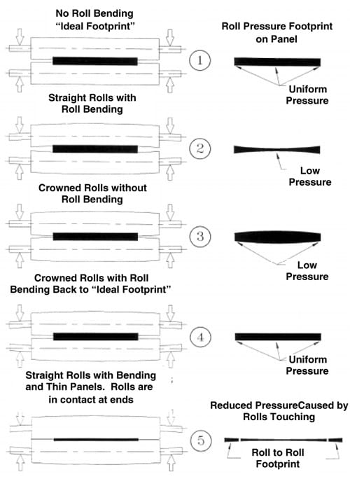
The amount of bending can be estimated by looking at the “footprint” or contact area of the roll nip. In the attached figures, the drawing on the left is a front view of the edge of a panel between two lamination rolls. The drawing on the right is the footprint of the rolls on the panel. This is what would appear if the roll had been inked and had been pressed down against the panel, leaving an impression of the roll on the panel. The width of this footprint is a measure of the pressure applied. Since the rubber covering compresses under pressure, the footprint widens as the pressure increases.
The pressure differences caused by roll bending can be compensated for with rolls which are “crowned.” A crowned roll has a rubber covering which is thicker in the center than at the edges and changes gradually from center to edge, resulting in a curved profile.
The first figure in the attached picture is an illustration of ” ideal” non-bending rolls and their nip footprint. This is physically impossible but is shown to illustrate that the shape of the footprint for the ideal case is a rectangle. The constant width is evidence of uniform pressure across the panel width.
In Figure 2, ” real” rolls are illustrated, showing how they bend under load. The nip footprint is wider at the ends of the contact area, reflecting the higher pressure near the ends and the lower pressure at the center. Since conformat ion is highly dependent on this pressure, conformation at the center will be poorer than conformation at the edges of the panel. (Note that both the roll bending and the footprint shape are highly exaggerated in the pictures.)
If the “ideal” non-bend ing rolls are crowned (Figure 3) the footprint is widest at the center and tapers off at both ends indicating higher pressure at the center than at the edges.
Figure 4 shows crowned “real” rolls bending under load. The decrease in footprint at the center due to roll bending (as shown in Figure 2) is compensated for by the increase in center footprint of Figure 3. The combination restores the footprint to a rectangular shape. It is important that the amount of crown be correct for the amount of bending. Too much crown and the footprint will still look like Figure 3, while too little crown will leave uncompensated pressure differences. It is best to err on the low side, since you will see some improvement even if the crown is too small. A crown which is too large cannot be easily corrected except by increasing the pressure at the roll air cylinders. Too much crown can also cause the rolls to cock. This is caused by slight differences in the closing speed of the rolls. Cocked rolls will result in poor conformation along one side of the panel.
The amount of roll bending changes with the width of the panel being laminated. The rolls bend more with narrow panels than with wide panels. A narrow panel, however, contacts only the least curved portion of the rolls (in the center) and the pressure difference from center to edge is less than for a wider panel. A narrow panel also has the advantage of concentrating the available pressure over a smaller area, resulting in generally better conformation.
The thickness of the panel can also affect the footprint. If the material to be laminated is very thin, as with some innerlayer laminate, the rolls will be in contact beyond the edges of the panel. This reduces the total load actually applied to the material. While roll bending will be reduced because the rolls are touching, the lower overall pressure will reduce conformation across the whole panel. Figure 5 shows how the footprint is affected by roll contact outside the panel width.
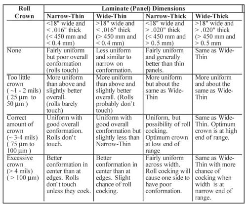
The amount of crown needed depends on panel thickness and width as mentioned above, by the amount of force applied by the loading cylinders, and by the moment of inertia of the rolls and the Modulus of Elasticity of the roll material. The last three of these factors are fixed by laminator design. Generally, ASL-24 laminators operating at a clamp pressure of 5 Bars need less than 4 mils (100 μm) crown (total difference in diameter from center to edges). Other laminators, which have different roll construction and different roll loading arrangements, may require more or less crown. In all cases a small amount of crown is preferable to excessive crown. The following table is a guide to selecting crowns for ASL-24 laminator rolls. The column for material thicknesses falling between .016″ and .020″ (between 0.4mm and 0.5mm) depends on whether the rolls touch or not. If they touch, use the <.016″ (0.4mm) column. If they do not touch, use the >.020″ (0.5mm) column. This table was constructed from tests performed with rolls having a 4-mil (100 μm) crown and involved measuring the number and location of conformation defects. For straight rolls, the defects clustered near the center of the panels due to the lower pressure there. With the crowned rolls, the number of defects along the edges was higher than the number near the center unless the pressure was increased to 7 Bars. At 7 Bars pressure the distribution of defects was nearly uniform across the panels. Based on the 4-5 Bars pressure normally used, the 4-mil (100 μm) crown appears excessive. Less crown, 2 to 3 mils (50-75 μm), is recommended as a starting point.

The greatest advantage from crowned rolls will probably be with very thin, relatively narrow (>19″ or 475mm) innerlayer material. The crowns will increase the overall pressure during lamination, improving conformation over the whole panel. With wider and thicker panels, the main improvement will be in uniformity.


