


Tactile sensing
~Credit to Dr. RM Crowder
Touch and tactile sensor are devices which measures the parameters of a contact between the sensor and an object. This interaction obtained is confined to a small defined region. This contrasts with a force and torque sensor that measures the total forces being applied to an object. In the consideration of tactile and touch sensing, the following definitions are commonly used:
Touch Sensing
This is the detection and measurement of a contact force at a defined point. A touch sensor can also be restricted to binary information, namely touch, and no touch.
Tactile Sensing
This is the detection and measurement of the spatial distribution of forces perpendicular to a predetermined sensory area, and the subsequent interpretation of the spatial information. A tactile-sensing array can be considered to be a coordinated group of touch sensors.
Slip
This is the measurement and detection of the movement of an object relative to the sensor. This can be achieved either by a specially designed slip sensor or by the interpretation of the data from a touch sensor or a tactile array.
Tactile sensors can be used to sense a diverse range of stimulus ranging from detecting
the presence or absence of a grasped object to a complete tactile image. A tactile sensor
consists of an array of touch sensitive sites, the sites may be capable of measuring more
than one property. The contact forces measured by a sensor are able to convey a large
amount of information about the state of a grip. Texture, slip, impact and other contact
conditions generate force and position signatures, that can be used to identify the state of
a manipulation. This information can be determined by examination of the frequency
domain, and is fully discussed in the literature.
As there is no comprehensive theory available that defines the sensing requirements for a
robotic system, much of the knowledge is drawn from investigation of human sensing,
and the analysis of grasping and manipulation. Study of the human sense of touch
suggests that creating a gripper incorporating tactile sensing requires a wide range of
sensors to fully determine the state of a grip. The detailed specification of a touch sensor
will be a function of the actual task as it is required to perform. Currently no general
specification of a touch or tactile sensor exists the following can be used as an excellent
basis for defining the desirable characteristics of a touch or tactile sensor suitable for the
majority of industrial applications:
- A touch sensor should ideally be a single-point contact, through the sensory area can be any size. In practice, an area of 1-2 mm2 is considered a satisfactory compromise between the difficulty of fabricating a sub-miniature sensing element and the coarseness of a large sensing element.
- The sensitivity of the touch sensor is dependent on a number of variables determined by the sensor's basic physical characteristic. In addition the sensitivity may also be the application, in particular any physical barrier between the sensor and the object. A sensitivity within the range 0.4 to 10N, together with an allowance for accidental mechanical overload, is considered satisfactory for most industrial applications.
- A minimum sensor bandwidth of 100 Hz.
- The sensor‘s characteristics must be stable and repeatable with low hysteresis. A linear response is not absolutely necessary, as information processing techniques can be used to compensate for any moderate non-linearities.
- As the touch sensor will be used in an industrial application, it will need to be robust and protected from environmental damage.
- If a tactile array is being considered, the majority of application can be undertaken by an array 10-20 sensors square, with a spatial resolution of 1-2 mm.
In a dexterous end effector, the forces and relative motions between the grasped object and the fingers need to be controlled. This can be achieved by using a set of sensors capable of determining in real time, the magnitude, location, orientation of the forces at the contact point. This problem has been approached by using miniature force and torque sensors inside the finger tips, to provide a robot with an equivalent to the kinesthetic sense found in humans. The integration of skin like and kinesthetic-like sensing will result in robots being equipped with artificial haptic perceptions.
Touch sensor technology
Many physical principles have been exploited in the development of tactile sensors. As the technologies involved are very diverse, this chapter can only consider the generalities of the technology involved. In most cases, the developments in tactile sensing technologies are application driven. It should be recognised that the operation of a touch or tactile sensor is very dependant on the material of the object being gripped.. The sensors discussed in this chapter are capable of working with rigid objects. However if non-rigid material is being handled problems may arise. Work has shown that conventional sensors can be modified to operate with non-rigid materials.
Mechanically based sensors
The simplest form of touch sensor is one where the applied force is applied to a conventional mechanical micro-switch to form a binary touch sensor. The force required to operate the switch will be determined by the its actuating characteristics and any external constraints. Other approaches are based on a mechanical movement activating a secondary device such as a potentiometer or displacement transducer.
Resistive based sensors
The use of compliant materials that have a defined force-resistance characteristics have received considerable attention in touch and tactile sensor research. The basic principle of this type of sensor is the measurement of the resistance of a conductive elastomer or foam between two points. The majority of the sensors use an elastomer that consists of a carbon doped rubber.
In the above sensor the resistance of the elastomer changes with the application of force, resulting from the deformation of the elastomer altering the particle density.
If the resistance measurement is taken between opposing surfaces of the elastomer, the
upper contacts have to be made using a flexible printed circuit to allow movement under
the applied force. Measurement from one side can easily be achieved by using a dot-andring
arrangement on the substrate. Resistive sensors have also been developed using
elastomer cords laid in a grid pattern, with the resistance measurements being taken at the
points of intersection. Arrays with 256-elements have been constructed. This type of
sensor easily allows the construction of a tactile image of good resolution.
The conductive elastomer or foam based sensor, while relatively simple does suffer from
a number of significant disadvantages:
• An elastomer has a long nonlinear time constant. In addition the time constant of
the elastomer, when force is applied, is different from the time constant when the
applied force is removed.
• The force-resistance characteristic of elastomer based sensors are highly
nonlinear, requiring the use of signal processing algorithms.
• Due to the cyclic application of forces experience by a tactile sensor, the resistive
medium within the elastomer will migrates over a period of time. Additionally,
the elastomer will become permanently deformed and fatigue leading to
permanent deformation of the sensor. This will give the sensor a poor long-term
stability and will require replacement after an extended period of use.
Even with the electrical and mechanical disadvantages of conductive elastomers and
foams, the majority of industrial analogue touch or tactile sensors that have been based
on the principle of resistive sensing. This is due to the simplicity of their design and
interface to the robotic system.
Force sensing resistor
A force sensing resistor is a piezoresistivity conductive polymer, which changes
resistance in a predictable manner following application of force to its surface. It is
normally supplied as a polymer sheet which has had the sensing film applied by screen
printing. The sensing film consists of both electrically conducting and non-conducting
particles suspended in matrix. The particle sizes are of the order of fraction of microns,
and are formulated to reduce the temperature dependence, improve mechanical properties
and increase surface durability. Applying a force to the surface of a the sensing film
causes particles to touch the conducting electrodes, changing the resistance of the film.
As with all resistive based sensors the force sensitive resistor requires a relatively simple
interface and can operate satisfactorily in moderately hostile environments.
Force sensing resistor
The capacitance between two parallel plates is given by:
A
C= ———
d
where A is the plate area, d the distance between the plates, and e the permittivity of the
dielectric medium. A capacitive touch sensor relies on the applied force either changing
the distance between the plates or the effective surface area of the capacitor. In such a
sensor the two conductive plates of the sensor are separated by a dielectric medium,
which is also used as the elastomer to give the sensor its force-to-capacitance
characteristics.
To maximize the change in capacitance as force is applied, it is preferable to use a high
permittivity, dielectric in a coaxial capacitor design. . In this type of sensor, as the size is
reduced to increase the spatial resolution, the sensor‘s absolute capacitance will decrease.
With the limitations imposed by the sensitivity of the measurement techniques, and the
increasing domination of stray capacitance, there is an effective limit on the resolution of
a capacitive array. The figure shows the cross section of the capacitive touch transducer
in which the movement of a one set of the capacitors' plates is used to resolve the
displacement and hence applied force. The use of a highly dielectric polymer such as
polyvinylidene fluoride maximizes the change capacitance. From an application
viewpoint, the coaxial design is better as its capacitance will give a greater increase for an
applied force than the parallel plate design

To measure the change in capacitance, a number of techniques can be, the most popular is based on the use of a precision current source. A second approach is to use the sensor as part of a tuned or L.C. circuit, and measure the frequency response. Significant problem with capacitive sensors can be caused if they are in close proximity with the end effector‘s or robot‘s earthed metal structures, this leads to stray capacitance. This can be minimized by good circuit layout and mechanical design of the touch sensor. It is possible to fabricate a parallel plate capacitor on a single silicon slice, this can give a very compact sensing device, this approach is discussed below.
Magnetic based sensor
There are two approaches to the design of touch or tactile sensors based on magnetic
transduction. Firstly, the movement of a small magnet by an applied force will cause the flux density at the point of measurement to change. The flux measurement can be made
by either a Hall effect or a magnetoresistive device. Second, the core of the transformer
or inductor can be manufactured from a magnetoelastic material that will deform under
pressure and cause the magnetic coupling between transformer windings, or a coil‘s
inductance to change. A magnetoresistive or magnetoelastic material is a material whose
magnetic characteristics are modified when the material is subjected to changes in
externally applied physical forces. The magnetorestrictive or magnetoelastic sensor has a
number of advantages that include high sensitivity and dynamic range, no measurable
mechanical hysteresis, a linear response, and physical robustness.
If a very small permanent magnet is held above the detection device by a complaint
medium, the change in flux caused by the magnet's movement due to an applied force can
be detected and measured. The field intensity follows an inverse relationship, leading to a
nonlinear response, which can be easily linearized by processing. A one-dimensional
sensor where a row of twenty hall effect devices placed opposite a magnet has been
constructed. A tactile sensor using magnetoelastic material has been developed, where
the material was bonded to a substrate, and then used as a core for an inductor. As the
core is stressed, the material‘s susceptibility changed, which is measured as a change in
the coil‘s inductance.
Optical Sensors
The rapid expansion of optical technology in recent years has led to the development of a
wide range of tactile sensors. The operating principles of optical-based sensors are well
known and fall into two classes:
• Intrinsic, where the optical phase, intensity, or polarization of transmitted light are
modulated without interrupting the optical path
• Extrinsic, where the physical stimulus interacts with the light external to the
primary light path.
Intrinsic and extrinsic optical sensors can be used for touch, torque, and force sensing.
For industrial applications, the most suitable will be that which requires the least optical
processing. For example the detection of phase shift, using interferometry, is not
considered a practical option for robotic touch and force sensors. For robotic touch and
force-sensing applications, the extrinsic sensor based on intensity measurement is the
most widely used due to its simplicity of construction and the subsequent information
processing. The potential benefits of using optical sensors can be summarized as follow:
Immunity to external electromagnetic interference, which is widespread in robotic
applications.
• Intrinsically safe.
• The use of optical fibre allows the sensor to be located some distance from the
optical source and receiver.
• Low weight and volume.
Touch and tactile optical sensors have been developed using a range of optical
technologies:
(a) Modulating the intensity of light by moving an obstruction into the light path.
The force sensitivity is determined by a spring or elastomer. To prevent cross-talk from external sources, the sensor can constructed around a deformable tube, resulting in a highly compact sensor:

In the reflective touch sensor below, the distance between the reflector and the plane of source and the detector is the variable. The intensity of the received light is a function of distance, and hence the applied force. The U shaped spring was manufactured from spring steel, leading to a compact overall design. This sensor has been successfully used in an anthropomorphic end effector:

A reflective sensors can be constructed with source-receiver fibre pairs embedded in an solid elastomer structure. As shown below, above the fibre is a layer of clear elastomer topped with a reflective silicon rubber layer. The amount of light reflected to the receiver is determined by applied force, that changes the thickness of the clear elastomer. For satisfactory operation the clear elastomer must have a lower compliance that the reflective layer. By the use of a number of matrix of transmitter-receiver pairs, the tactile image of the contact can be determined:

(b) Photoelasticity
Photoelasticity is the phenomena where stress or strain causes birefringence in an optically transparent materials. Light is passed through the photoelastic medium. As the medium is stressed, the photoelastic medium effectively rotates the plane of polarization and hence the intensity of the light at the detector changes as a function of the applied force. This type of sensor is of considerable importance in the measurement of slip.
Optical fibre based sensors
In the previous section, optical fibres where used are solely for the transmission of light to and from the sensor, however tactile sensors can be constructed from the fibre itself. A number of tactile sensors have been developed using this approach. In the majority of cases either the sensor structure was too big to be attached to the fingers of robotic hand or the operation was too complex for use in the industrial environment. A suitable design can be based on internal-state microbending of optical fibres. Microbending is the process of light attenuation in the core of fibre when a mechanical bend or perturbation (of the order of few microns) is applied to the outer surface of the fibre. The degree of attenuation depends on the fibre parameter‘s as well as radius of curvature and spatial wavelength of the bend. Research has demonstrate the feasibility of effecting microbending on an optical fibre by the application of a force to a second orthogonal optical fibre.
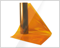
Piezoelectric sensors
Polymeric materials that exhibit piezoelectric properties are suitable for use as a touch or
tactile sensors, while quartz and some ceramics have piezoelectric properties, polymers
such as polyvinylidene fluoride (PVDF) are normally used in sensors.
Polyvinylidene fluoride is not piezoelectric in its raw state, but can be made piezoelectric
by heating the PVDF within an electric field. Polyvinylidene fluoride is supplied sheets between as 5 microns and 2 mm thick, and has good mechanical properties. A thin layer
of metalization is applied to both sides of the sheet to collect the charge and permit
electrical connections being made. In addition it can be moulded, hence PVDF has
number of attraction when considering tactile sensor material as an artificial skin.
Strain gauges in tactile sensors
A strain gauge when attached to a surface will detect the change in length of the material
as it is subjected to external forces. The strain gauge is manufactured from either resistive
elements (foil, wire, or resistive ink) or from semiconducting material. A typical resistive
gauge consists of the resistive grid being bonded to an epoxy backing film. If the strain
gauge is pre-stressed prior to the application of the backing medium, it is possible to
measure both tensile and compressive stresses. The semi-conducting strain gauge is
fabricated from a suitable doped piece of silicone, in this case the mechanism used for the
resistance change is the piezoresistive effect.
When applied to robotic touch applications, the strain gauge is normally used in two
configurations: as a load cell, where the stress is measured directly at the point of contact,
or with the strain gauge positioned within the structure of the end effector.
Silicon based sensors
Technologies for micromachining sensors are currently being developed world-wide. The
developments can be directly linked to the advanced processing capabilities of the
integrated circuit industry, that has developed fabrication techniques that allow the
interfacing of the non-electronic environment to be integrated through microelectromechanical
systems.. Though not as dimensionally rigorous as the more mature
silicon planer technology, micromachining is inherently more complex as it is involves
the manufacture of a three-dimensional object. Therefore the fabrication relies on
additive layer techniques to produce the mechanical structure.
The excellent characteristics of silicon, that has made micromachined sensors possible,
include a tensile strength comparable to steel, elastic to breaking point, and there is very
little mechanical hysteresis in devices made from as single crystal, a low thermal
coefficient of expansion.
To date it is apparent that microengineering has been applied most successfully to
sensors. Some sensor applications take advantage of the device-to-device or batch-tobatch
repeatability of wafer-scale processing to remove expensive calibration procedures.
Current applications are restricted largely to pressure and acceleration sensors, though
these in principle can be used as force sensors. As the structure is very delicate, there still
are problems in developing a suitable tactile sensor for industrial applications.
Smart Sensors
The most significant problem with the sensor systems discussed so far is that of signal processing. Researchers are therefore looking to develop a complete sensing system rather than individual sensors, together with individual interfaces and interconnections. This allows the signal processing to be brought as close as possible to the sensor itself or integrated with the sensor. Such sensors are generally termed smart sensors. It is the advances in silicon fabrication techniques which have enabled the recent developments in smart sensors. There is no single definition of what a smart sensor should be capable of doing, mainly because interest in smart sensors is relatively new. However, there is a strong feeling that the minimum requirements are that the sensing system should be capable of self diagnostics, calibration and testing. As silicon can be machined to form moving parts such as diaphragms and beams, a tactile sensor can in principal be fabricated on single piece of silicon. Very little commercial success has been obtained so far, largely due to the problems encountered in transferring the technology involved from the research laboratory to industry. In all tactile sensors their is a major problem of information processing, and interconnection. An array has 2n connection and individual wires, any reduction in interconnection requirements is welcomed due to ease of construction and increased reliability. A number of researchers have been addressing the problem of integrating a tactile sensor with integral signal processing. In this design the sensor‘s conductive elastomer sheet was placed over a substrate. The significant feature of this design is that the substrate incorporated VLSI circuitry so that each sensing element not only measures its data but processes it as well. Each site performs the measurements and processing operations in parallel. The main difficulty with this approach was the poor discrimination, and susceptibility to physical damage However, the VLSI approach was demonstrated to be viable, and alleviated the problems of wiring up each site and processing the data serially.
Multi-stimuli Touch Sensors
It has been assumed that all the touch sensors discussed in this section respond only to a force stimulus. However, in practice most respond to other external stimuli, in particular, temperature. If PVDF has to be used as a force sensor in an environment with a widely varying ambient temperature, there may be a requirement for a piece of unstressed PVDF to act as a temperature reference. It is possible for a sensor to respond both to force and temperature changes. This has a particular use for object recognition between materials that have different thermal conductivity, e.g., between a metal and a polymer. If the complexity of the interpretation of data from PVDF is unsuitable for an application, touch sensors incorporating a resistive elastomer for force, and thermistors for temperature measurement can be constructed. By the use of two or more force-sensitive layers on the sensor, which have different characteristics (e.g., resistive elastomer and PVDF), it is possible to simulate the epidermal and dermal layers of human skin.
