

Nip impressions actually save you money!
The use of nip impression papers to determine the actual nip widths of pairs of rolls under operating conditions is too infrequently used. Normally, if the web being processed appears to be uniform in moisture content as it leaves the process, it is assumed that all is working well along the line. Uneven pressure along the width of the roll caused by insufficient crown will not be detectable by tests on the finished product, provided the pressure is not high enough to actually start crushing the web being processed.
The effect of this uneven pressure, caused by lack of crown, or excessive loading for the crown used, will then become evident only by uneven wear and end–cracking of the rubber covered rolls, decreased felt life, poor paper formation, shady dyeing, etc. The time and labor spent in determining proper crowns for rubber covered rolls will be more than compensated for by improved performance and decreased maintenance costs.
Nip impression films are specifically designed to determine the actual working nip width of a pair of rolls under operating conditions. The impression taken may be used to determine the need for corrective measures, such as recrowning or refinishing, or to determine more satisfactory roll pressures for given operation. These impressions are permanent archives and can be retained to be referred to for future reference. Impressions to capture nip width are taken when rolls are not rotating (static impression), and only when the machine is down and the felts (if used) are removed or pushed to one side.
Taking nip width impressions are very simple!
3 easy steps:
A. Make certain that both the top and bottom rolls are clean and dry in the area in which the nip width impression is to be taken.
B. Remove films from box and unroll on bottom roll at line of contact between top and bottom roll. Make certain that carbon and paper are centered, so that nip impression is in center area of paper. If rolls are horizontal and on same vertical plane, the kit will normally remain on roll without use of tape. if rolls are offset or overhang, we–suggest the use of small strips of pressure sensitive tape to hold the sheets in proper position.
C. Bring the rolls together gently at first, then gradually load to normal operating pressure. Wait for approximately one minute after pressure has normalized before separating rolls. Nip impression paper may then be removed and disposed of and the nip width impression evaluated.
Types of Impressions:
Determination of Roll Crown from Nip Width Impression
Having determined the nip widths under the desired loadings and ‘knowing the diameters of our rolls, we can determine the additional crown for the roll by use of the following formula:
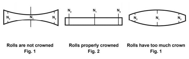
C = additional crown required i.e., the difference in diameter between the center and 2 in. in from the ends of the roll.
N₁ = nip width at center of roll
N₂ = nip width 2 in. in from the ends of the roll
D₁ = diameter of top roll
D₂ = diameter of bottom roll the
C= (N²₂ —— N²₁) (D₁ + D₂)
2D₁D₂
or if rolls have equal diameters
C = (N²₂ — N²₁)
D
As an example let us assume that we have two 12−in. diameter rolls, and we find that the nip widths are 0.9−in. on the ends and 0.7−in. at the center under the loading at which we desire to run the rolls. Then by our formula since:
N₁ = 0.7
N₂ = 0.9
D = 12
C = (0.9² 0.7²) = 0.81 0.49 = 0.32 = 0.027 in
12 12 12
lf our rolls were originally ground straight face we would now put a crown of 0.027−in. into the rubber. If the crown were originally 0.030−in. it would be increased to 0.057−in. If the situation were reversed and the nip at the center [N1] were 0.9−in. and the nip at the ends [N2l were 0.7−in., our indicated crown would then be − 0.027−in. indicating that the nip already contained toe much crown. Now if the crown of our roll were 0.03G−in. then the proper crown would be 0.003−in.
It is frequently helpful to determine crowns for various loadings so that if one desires to change the loading then the proper crown for the roll will be immediately available. The crown as determined above is, of course, the combined crown for the two rolls involved. The amount of this crown put into the top and the bottom roll will depend on the individual machine and operation.
