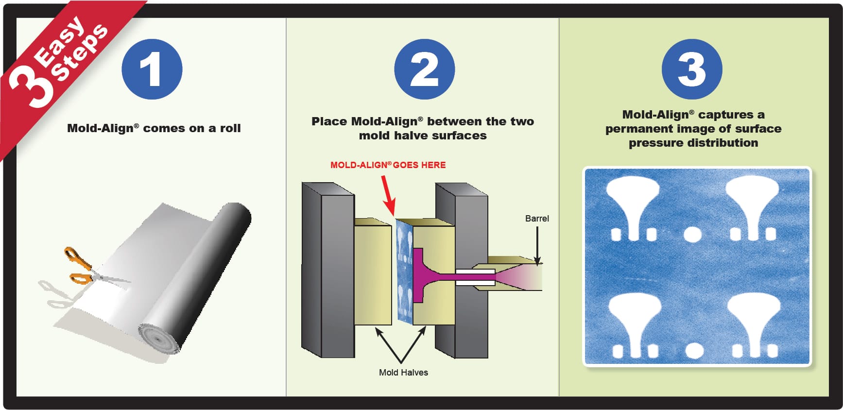
Mold-Align® is a unique, affordable and easy to use tool that reveals pressure distribution between mold platens.
Articles
Of the hundreds of variables involved in injection molding, clamping mechanisms and platens often get less attention than they deserve. Good clamp performance is critical to minimize cycle times, optimize part quality, and maintain process consistency. Alignment and uniformity of the mold halves, platens, and clamping system is therefore critical. Whether an alignment problem stems from the mold parting line, the platens, or the clamping mechanism and tiebars, the results can be unnecessary machine wear, mold damage, broken tiebars, mold flash, and scrap parts.
Parting line aligned and uniform?

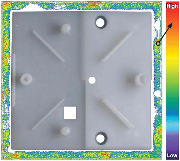
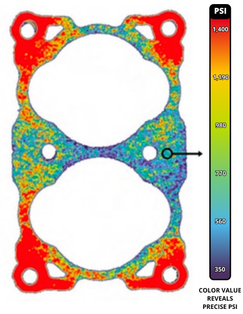
One way to ensure proper mating of the tool halves at the parting line is simply by having a level molding machine and parallel platens. Leveling a machine requires three machinist levels. If you have shorts and flash, you could have a mold or clamping alignment problem. This may not be the case if you are running a high-speed, thin-wall product-the problem may be simply not enough clamp force. To help establish whether flash stems from a mold or clamp alignment issue, check parting-line mating. In one typical check for uniform clamp pressure at the parting line, blueing agent applied to one mold half will transfer to the other if there is contact at the parting line, but it will not distinguish between low or high touch force. More detailed information can be obtained with Mold-Align® paper, which changes color relative to the amount of contact force. Mold-Align® is an extremely economical and practical solution for determining proper mold alignment. Mold-Align® is a self contained (single sheet) paper that is quickly implemented, requires no training, and reveals a high resolution image of pressure distribution and void spots between mold plates.
“Mold-Align® is providing valuable insight on the causes of excessive non- engineered flash we are seeing in our manufacturing process. We have determined that some of the moulds are deformed, probably due to worn insulation board on a particular press. We are now in a better position to remedy these problems, based on the qualitative information obtained from this product.”
~Omer Bicer
Mackay
| Roll dimensions | |
| 10.5 in. x 50 ft. (26.7 cm x 15.2 m) | |
| 30.0 in. x 50 ft. (76.2 cm x 15.2 m) | |
| Specifications | |
| Thickness | 4 mils (0.1016 mm) |
| Usable Humidity Range | 10-90% RH |
| Pressure Range | 1,000 – 6,000 PSI (70 – 422 kg/cm2) |
| Temperature Limit | 200°F (93°C) |


