


A Uniform Pressure Apparatus for Micro/Nanoimprint Lithography Equipment
Jian-Shian Lin*,**, Chieh-Lung Lai*, Ya-Chun Tu*, Cheng-Hua Wu*, and Yoshimi Takeuchi**
*Mechanical and System Research Laboratories, Industrial Technology Research Institute
195 Chung Hsing Rd., Sec.4 Chu Tung, HsinChu, Taiwan 310, R.O.C.
E-mail: [email protected]
**Department of Mechanical Engineering, Osaka University
2-1 Yamadaoka, Suita, Osaka 565-0871, Japan
[Received September 17, 2008; accepted November 6, 2008]
Nanoimprint lithography (NIL) has overcome the limitation of light diffraction. It is capable of printing features less than 10nm in size with high lithographic resolution, high manufacturing speed, and low production cost. The uniformity of pressure, however, remains a critical issue. To improve the uniformity of pressure, we developed a flexible uniform pressure component based on Pascals Law. When external force is applied to this component, uniform pressure is delivered to the mold and substrate. Average pressure over the embossed area using our improved nanoimprint equipment deviates by only 3.15%.
Keywords: nanoimprint, uniform pressure, lithography
1. Background
1.1. Technical Introduction
Nanoimprint lithography (NIL) involves pressing a
nanomold mechanically under high temperature and pressure
to duplicate nanostructures on a substrate to which
polymer photoresist is applied. Processing resolution is
limited by the critical mold size [14].
1.2. Critical Development
Since the introduction of NIL in 1995, many innovative
nanoimprint researches have been done [5] using mold
imprinting in which lithographic resolution reached 5 nm
[6]. Due to uneven imprint (Fig. 1), molds or substrates
may be bent or distorted the major cause of asymmetrical
imprinting depth, partial microstructure twisting, and
deformation. Microstructures may also be damaged while
the mold is being removed from the substrate when imprinting
is uneven. If the mold and substrate do not remain
parallel (Fig. 2), the microstructure angle differs
at each imprinting, compromising quality and damaging
nanostructures on the mold or substrate due to excessive
inclination. Gao et al. have developed air cushion pressing
(ACP) in which the mold and substrate are pressed
together by gas pressure rather than a solid plate. Their
method produces much more uniform measured pressure distribution than conventional hot embossing [7]. Jang
et al. have designed fluid-based heating and pressing for
hot microembossing, which makes heat and pressure distributed
over the embossed areamore uniform than in conventional
hot embossing, and fluid-heated hot embossing
requires a much shorter cycle time [8, 9].

Fig. 1. Uneven imprinting.

Fig. 2. Nonparallel imprinting.
2. Uniform Pressure Apparatus Design
To solve these problems, we propose an innovative imprinting control using a uniform pressure apparatus that precisely controls imprinting depth and uniformity, thereby improving imprinting quality (Fig. 3).
Our design is based on Pascals Law that is, pressure is equal at any point within an enclosed space filled with hydrostatic fluid and uses a flexible uniform fluidfilled pressure element (Fig. 4). Exerting force on this element delivers uniform pressure to the mold and substrate (Fig. 5).

Fig. 3. Nanoimprint.

Fig. 4. Rubber bag.

Fig. 5. Uniform pressure apparatus.

Fig. 6. Nanoimprint equipment.
The nanoimprint equipment using the uniform pressure apparatus based on Pascals Law consists of a cover, a closed end, a uniform pressure element, a first plate, a flange, a mold, forming materials, a substrate, and a second plate (Fig. 6). The cover is hollow inside with the open end having a flange. The top side of the first plate has a flange larger than the opening end of the cover. This flange is embedded inside the cover so that the first plate is kept from falling off the cover. The first plate carries the nanostructure mold. The uniform pressure element, located above the first plate opposite to the mold, is made of flexible fluid-filled material. Fluid inside the element remains at a constant overall pressure so that the element simultaneously provides uniform pressure and parallel distance between the mold and substrate. The second plate holds the substrate with forming materials. A power source moves the cover and first plate toward the second plate, providing the force during imprinting (Fig. 7).

Fig. 7. Nanoimprint process.
In imprinting (Fig. 7a), the substrate is positioned in advance together with the mold. Power is turned on (Fig. 7b) and the cover, first plate, and mold are driven toward the substrate on the second plate so that the mold directly contacts the substrate parallel to it. The cover moves toward the uniform pressure element after the first plate leaves the cover with the flange, and the closed end of the cover eventually contacts the uniform pressure element. Force consistently exerted on the cover is transferred to the uniform pressure element (Fig. 7c), compressing the element to distribute all required imprinting force at the designated value. The power source then moves in reverse to remove the closed end of the cover away from the uniform pressure element and leads the mold off the substrate to complete imprinting (Figs. 7d and 8).

Fig. 8. Uniform pressure nanoimprint apparatus.
3. Nanoimprint Experiments
To confirm the influence of the uniform pressure element on imprinting, we conduct experiments using a polished silicon wafer for both the mold and substrate. We insert pressure-measurement film (Prescale, Fujifilm) between the mold and substrate to directly measure imprint pressure distribution. When the power source transmits force, the flexible uniform pressure element distributes pressure evenly to the mold and substrate via hydraulic pressure. After imprinting ends, microcapsules on the pressure-measurement film are broken and coloring materials inside the capsule react with color-development materials. The number of broken microcapsules in a given area is directly proportional to the pressure exerted, so pressure distribution is presented as fading color. We then use a concentration meter and a pressure converter to quantify pressure distribution and to analyze its uniformity.
3.1. Results of Conventional Hot Embossing Imprinting
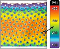
Pressure distribution in conventional hot embossing shows that variations in color fading are large because most hot embossing equipment does not take pressure uniformity into account, with only the surface of the plates hosting the mold and substrate polished (Fig. 9). Plates used too long may also become partially deformed, making pressure uniformity unsatisfactory.

Fig. 9. Pressure distribution in conventional hot embossing.

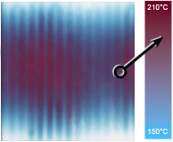
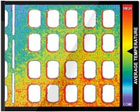
Fig. 10. Pressure distribution of hot embossing imprinting with uniform pressure apparatus.
3.2. Hot Embossing Imprinting with Uniform Pressure Apparatus
According to pressure distribution in hot embossing using our uniform pressure apparatus, we clearly observe that color fading varies less compared to conventional hot embossing (Figs. 9 and 10). The flexible uniform pressure element transmits uniform pressure directly via fluid. Even if equipment is used for a long time, pressure uniformity is maintained and plate bending presents no concern.
3.3. Comparison of Results
We designate 13 locations as reference points on the pressure film (Fig. 11) and quantify them via the pressure converter as follows:

N denotes the sampling number; xi represents the pressure of point i; x is the mean pressure, and Ei is the average deviation of point i (Fig. 12). In conventional hot embossing, the pressure uniformity is unsatisfactory: peak pressure varies 4 times from R = 1 to R = 0 and deviation averages 40.84%. Using our uniform pressure apparatus, pressure variation is significantly reduced and average deviation is merely 3.15%.

Fig. 11. Reference points.

Fig. 12. Pressure quantification analysis.
4. Conclusions
We have proposed a uniform pressure design concept and demonstrated its feasibility through experiments. Imprinting resulting from the pressure-measurement film shows that the pressure uniformity of conventional hot embossing equipment is unsatisfactory, deviating at an average of up to 40.84%. The uniform pressure element we designed significantly improves pressure uniformity, reducing average deviation to just 3.15%.
References:
- S. Y. Chuo, P. R. Krauss, and P. J. Renstrom, Imprint of sub-25nm vias and trenches in polymers, Applied Physics Letter, Vol.67, No.21, pp. 3114-3116, 1995.
- D. H. Raguin and G. Michael Morris, Analysis of antireflectionstructured surfaces with continuous one-dimensional surface profiles, Applied Optics, Vol.32, No.14, pp. 2582-2598, 1993.
- E. Noponen and J. Turunen, Binary high-frequency-carrier diffractive optical elements: electromagnetic theory, Journal of the Optical Society of America A, Vol.11, No.3, pp. 1087-1096, 1994.
- S. S. Wang, R. Magnusson, J. S. Bagby, and M. G. Moharam, Guided-mode resonances in planar dielectric-layer diffraction gratings, Journal of the Optical Society of America A, Vol.7, No.8, pp. 1470-1474, 1990.
- S. Y. Chou, P. K. Krauss, and P. J. Renstrom, Nanoimprint lithography, American Vacuum Society, J. Vac. Sci. Technol. B, Vol.14, No.6, pp. 4129-4133, 1996.
- M. D. Austin, H. Ge, W.Wu, M. Li, Z. Yu, D. Wasserman, S. A. Lyon, and S. Y. Chou, Fabrication of 5 nm linewidth and 14 nm pitch features by nanoimprint lithography, Applied Physics Letters, Vol.84, No.26, pp. 5299-5301, 2004.
- H. Gao, H. Tan, W. Zhang, K. Morton, and S. Y. Chou, Air Cushion Press for Excellent Uniformity, High Yield, and Fast Nanoimprint Across a 100 mm Field, NANO LETTERS, Vol.6, No.11, pp. 2438-2441, 2006.
- J. H. Chang and S. Y. Yang, Gas pressurized hot embossing for transcription of Micro-Feature, Microsystem Technologies, Vol.10, pp. 76-80, 2003.
- J. H. Chang and S. Y. Yang, Development of fluid-based heating and pressing for micro hot embossing, Microsystem Technologies, Vol.11, pp. 396-403, 2005.
