


MOUS Boron Nitride Spacer Pressure-X Test Procedure
The following is a brief test procedure for the Pressure-X compression test of the boron nitride spacers for the MUOS RRF and Squareax Subsystems.
Note: Squareax Assembly SP940133-002 (Figure 1) with Boron Nitride Spacers at 12 inch spacing (Figure 2) will be used for all pressure tests.
Test Preparation
- Clean all machined aluminum parts thoroughly prior to assembly.
- Pressure-X Film: a. Cut Medium Pressure-X film into 1.0 x .75 strips (Qty 20).
b. Cut High Pressure-X film into 1.0 x .75 strips (Qty 20)
c. Cut Medium Pressure-X film into .4 x .75 strips (Qty 20).
d. Cut High Pressure-X film into .4 x .75 strips (Qty 20)
Pressure-X Film Pressure Ranges
Film Type Pressure RangeUltra Low 28-85 psi
Super Low 70-350 psi
Low 350-1,400 psi
Medium 1,400-7,100 psi
High 7,100-18,500 psi
Super High 14,400-43,200 psi
Pressure Test #1: Housing Bottom
- Record time, temperature, and humidity.
- Place squareax housing (Figure 3) on workbench.
- Place strips of High Pressure-X film (7,100-18,500 psi) at bottom of housing (Figure 8, Orange) at each of the qty 3 spacer locations (Figure 2).
- Carefully install bottom Boron Nitride spacers into housing (Figure 4). Ensure that strips of Pressure-X film remain underneath bottom spacers. Do not touch spacers with bare hands, use gloves!
- Install inner conductor onto the bottom Boron Nitride spacers previously installed (Figure 5).
- Carefully install top Boron Nitride spacers onto inner conductor (Figure 6). Do not touch spacers with bare hands, use gloves!
- At each of the qty 3 spacer locations, measure spacer height with respect to the housing/cover mating plane. Record this height as spacer interference.
- Use shim stock as required to reduce the spacer interference to approximately .002. Place shim stock along entire run of squareax assembly at the housing/cover mating plane to fully support cover.
- Carefully install cover onto housing (Figure 7) using the following hardware: a. Screw: NAS1352N04-5
- Again, record time, temperature, and humidity.
- Carefully remove cover from housing by removing hardware.
- Carefully remove top Boron Nitride spacers off of inner conductor. Do not touch spacers with bare hands, use gloves! Inspect spacers for damage. Be sure to note which spacer location each spacer was installed at (Figure 2), however, do not mark part. Spacers will be placed in same location in future tests if no damage is found.
- Carefully remove inner conductor off of bottom Boron Nitride spacers.
- Carefully remove bottom Boron Nitride spacers off of Pressure-X film strips. Do not touch spacers with bare hands, use gloves! Inspect spacers for damage. Again, be sure to note which spacer location each spacer was installed at (Figure 2), however, do not mark part. Spacers will be placed in same location in future tests if no damage is found.
- Lastly, remove the 3 Pressure-X film strips from the inside of the housing. Record the following information for each strip: a. Pressure Test Number
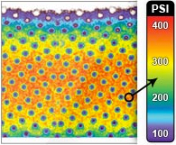
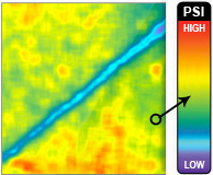
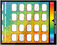
- Determine approximate PSI applied across the surface area of the film by using the Color Correlation Manual for Pressure Interpretation.
- If results are unsatisfactory, test may be repeated. Repeat steps 1 thru 16 using film type (High, Medium, etc.) as specified per engineering direction.
- Repeat test except vary the spacer interference (Step 8) in each additional test using shim stock as required. Additional spacer interferences to be determined by engineering.
b. Lock Washer: MS35338-135
c. Washer: NAS620C4L
b. Corresponding spacer location it was taken from (Figure 2)
Pressure Test #2: Housing Cover
- Record time, temperature, and humidity.
- Place squareax housing (Figure 3) on workbench.
- Carefully install bottom Boron Nitride spacers into housing (Figure 4). Do not touch spacers with bare hands, use gloves! Use same spacers as previously used if no damage to spacers if found. Place spacers in the same location as they were in Pressure Test #1.
- Install inner conductor onto the bottom Boron Nitride spacers previously installed (Figure 5).
- Carefully install top Boron Nitride spacers onto inner conductor (Figure 6). Do not touch spacers with bare hands, use gloves! Use same spacers as previously used if no damage to spacers if found. Place spacers in the same location as they were in Pressure Test #1.
- At each of the qty 3 spacer locations, measure spacer height with respect to the housing/cover mating plane. Record this height as spacer interference.
- Place strips of High Pressure-X film (7,100-18,500 psi) on top of all top Boron Nitride spacers (Figure 8, Green) at each of the qty 3 spacer locations (Figure 2).
- Use shim stock as required to reduce the spacer interference to approximately .002. Note: Be sure to take into account the thickness of the pressure-x film (.004) that was placed on top of each spacer in step 7. Place shim stock along entire run of squareax assembly at the housing/cover mating plane to fully support cover.
- Carefully install cover onto housing (Figure 7) using the following hardware: a. Screw: NAS1352N04-5
- Again, record time, temperature, and humidity.
- Carefully remove cover from housing by removing hardware.
- Next, remove the 3 Pressure-X film strips from the top of the top Boron Nitride spacers. Record the following information for each strip: d. Pressure Test Number
- Carefully remove top Boron Nitride spacers off of inner conductor. Do not touch spacers with bare hands, use gloves! Inspect spacers for damage. Be sure to note which spacer location each spacer was installed at (Figure 2), however, do not mark part.
- Carefully remove inner conductor off of bottom Boron Nitride spacers.
- Carefully remove bottom Boron Nitride spacers off of Pressure-X film strips. Do not touch spacers with bare hands, use gloves! Inspect spacers for damage. Again, be sure to note which spacer location each spacer was installed at (Figure 2), however, do not mark part.
- Determine approximate PSI applied across the surface area of the film by using the Color Correlation Manual for Pressure Interpretation.
- If results are unsatisfactory, test may be repeated. Repeat steps 1 thru 16 using film type (High, Medium, etc.) as specified per engineering direction.
- Repeat test except vary the spacer interference (Step 8) in each additional test using shim stock as required. Additional spacer interferences to be determined by engineering.
b. Lock Washer: MS35338-135
c. Washer: NAS620C4L Ensure that strips of Pressure-X film remain above top spacers. Torque fasteners to 7 to 9 in-lbs.
e. Corresponding spacer location it was taken from (Figure 2)
Pressure Test #3: Inner Conductor Bottom
Repeat steps as above except using Pressure-X film at location #3 (Figure 8)
Pressure Test #4: Inner Conductor Top
Repeat steps as above except using Pressure-X film at location #3 (Figure 8)

Figure 1 Test stand used the in measuring of kinetic energy exerted on protective mats. (Courtesy E. Maklewska)
Figure 2: Squareax Spacer Layout (Housing cover removed)

Figure 3: Squareax Housing
Figure 4: Installation of Bottom Boron-Nitride Spacers

Figure 5: Installation of Inner Conductor
Figure 6: Installation of Top Boron-Nitride Spacers

Figure 7: Installation of Housing Cover

Figure 8: Squareax Cross-Section; Pressure-X Film Locations
Get a free pressure indicator sample for Composite Layup application.
