


Measurement of the Dynamic Center of Pressure of a Brake Pad During a Braking Operation
John D Fieldhouse, Naveed Ashraf and Chris Talbot - The University of Huddersfield
Thierry Pasquet, Pujol Franck and Rejdych Gabriel - Bosch Braking Systems, Drancy
ABSTRACT
This paper discusses the analysis and measurement of the dynamic centre of pressure of a brake pad during a normal braking event. The technique is unique in its design and implementation. The process is progressive whereby the interface static measurements are first taken and then dynamic testing is carried out under braking. Two different measurement systems are considered during the analysis with one used to measure the center of pressure. Both the in-board and out-board pads are measured for wear but the piston pad was selected for pressure measurements. Validation of the spragging process is undertaken on both test rigs and vehicle trials. Pad wear measurements complement the collective information. The results show the position of the centre of pressure to vary considerably during a braking event, both radially and axially along the pad. The variable "instability envelope" is related to the caliper mounting geometry which is subsequently compared to the effective "spragging angle" and the generation of brake noise. It is seen that by careful selection of the backplate abutment friction level the centre of pressure may be controlled to always fall within the "stable envelope" region.
INTRODUCTION
Disc brake noise is accepted to be a complex subject but it is known from the vast range of literature already published on the subject that the principal vibration characteristic of the disc is a diametrical mode. It may be shown (1) that in all cases of disc brake noise, whether the system is a sliding fist or rigid type caliper, the dynamic noise frequency may be related directly to the free mode vibration characteristic of the disc. In an attempt to explain the mechanisms involved a variety of mathematical models have been proposed, each of which go some way to explain the phenomenon over a specifjc frequency range. No s ngle mathematical model is currently available, or capable, of expressing differing mechanisms involved nor the vast range of interacting individual modes of vibrations which are inextricably linked by the brake system as a whole - the range is too broad 300Hz to 20,OOOHz for a dynamically unstable system. Regardless of how the mathematical models are limited they do allow the designer to introduce basic parameters and criteria at the design stage in an attempt to reduce the propensity of a brake to generate noise. By experience it is generally accepted that the higher the coefficient of friction at the pad/disc interface the greater the tendency will be for the brake to promote noise. This increase in friction coefficient increases the pad/disc interface force for a given pressure which in tum results in a greater braking torque. What it does not indicate is why there is a greater tendency for the disc to be excited in an out-ofplane mode, that is the movement of a disc vibrating in a diametrical mode order. It is some time ago that work by Spurr (2) had shown that a spragging affect could cause instability resulting in a variable lateral force if the sprag angle equated to the interface friction coefficient. Indeed the mechanism was represented by a semi-rigid strut which was inclined to a rubbing surface and pushed horlzonlallo the surface. When the inclination angle was set at the "sprag angle" of tan-1 μ or greater the strut would "dig-in". The normal force to the rubbing surface would then increase until flexure of the system allowed a secondary strut arrangement to be established whereby the sprag angle was reduced, the normal force would reduce and the strut would then continue to slide. Clearly because of the construction of the test rig, and the in-built flexibility of the members, the system was able to establish more than one sprag angle for it to work. The caliper is a similar system with a multiple of "sprag angles" and it is this mechanism in relation to the coefficient of friction at the pad/disc interface which this paper examines.
MAIN SECTION
For a caliper to be capable of spragging it is a requirement that the centre of pressure providing the force normal to the disc surface, as generated by the caliper pistons, would need to be offset from the centerline of the caliper mounting arrangement. The initial work will consider a theoretical approach as a means to explain how this may occur and then an empirical approach to examine the effects of an imposed offset center of pressure.
ANALYSIS OF ABUTMENT EFFECTS
It has been shown through co-planar analysis that the centre of pressure of a brake pad will vary along the pad axis due to the backplate/caliper finger friction variation during pad vibration. This in tum leads to a dynamic situation where the caliper may "sprag" causing out-ofplane vibration of the disc - hence noise. In a practical situation there will be an interaction between frictional affects at the pad abutment, between pad backplate and caliper finger, with the various dimensions of the braking pad when it is in equilibrium.
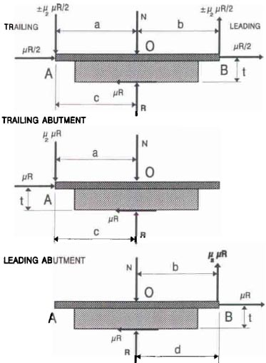
Figure 1 - Free body diagram of brake pad assuming coplanar frictional forces and differing abutment arrangement.
This equilibrium will vary with the pad abutment arrangement, a variety of abutment arrangements being shown in Figure 7. With such abutment arrangements it was possible to analyse the co-planar geometry with a trailing, leading or combined abutment arrangement. In practice the varying abutment was achieved by using a combined abutment pad and varying the abutment with appropriate shimming of the abutments.
A measure of the relationships involved for the different types of abutment may be established and compared if it is assumed that the various forces acting on the pad are coplanar as indicated in Figure 1. The full analysis is shown in previous work [3], which basically requires taking moments of the forces involved. The summary of the analysis is shown in Table 1 following where δ is the offset of center of pressure "R" to piston force "N".
Table 1 - Summary of analysis of abutment affects giving details of minimum value of μ2 to avoid offset pressure compensation, δ, to achieve eqUilibrium and also maximum offset as the pad/caliper finger interface coefficient of friction, μ2 tends to zero.

Table 1
Such analysis is supported by other researchers who have observed that noise propensity reduces as the pad wears [4].
EXPERIMENTAL INVESTIGATION OF IMPOSED OFFSET CENTRE OF PRESSURE
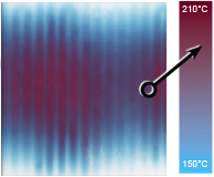
To examine the noise propensity of the brake to generate noise with a varying centre of pressure offset the contact position between the piston and piston pad was varied by using a O.75mm diameter silver steel wire inserted between the piston face and pad backplate as shown in Figure 2. The offset of the wire was varied 18mm either side of the piston centre, generally in increments of 6mm but in increments of 3mm at critical pOints. The wire was supported by a backing plate to prevent local indentation of the wire as a result of the piston wall.
The process of testing was, at each wire setting. to increase the disc surface temperature to over 1500C and then to vary the system pressure from 1 MPa, in increments of O.136MPa (20psi) down to zero and then back up to 1 MPa. The temperature was then allowed to fall 100C and the process repeated. During this cycle of events the noise frequency, duration and amplitude was noted over several reYoJullons of the disc 10 ensure a steady situation was being recorded. Between each new wire setting the pad was re-bedded to ensure each test began under similar conditions. The wire was repositioned and the whole test procedure repeated for the next setting. The test variable parameters were therefore the wire offset, the disc surface temperature and the system pressure with the measured results being the frequency of noise generated, the amplitude and the duration.

Figure 1 - Diagram showing position of wire to offset contact between piston and pad
A typical set of results is from such a test is shown in Figure 2 as a 3D representation and Figure 3 as a 20. It may be seen that with a leading offset of between 12mm and 15mm the system generally generated noise regardless of temperature, the more stable situations being obtained with a zero or trailing offset arrangement. It was further observed that as the temperature reduced, with a resulting increase in coefficient of friction, the critical offset changes from 12mm at 120aC (μ = 0.5 to 0.6) towards 15mm at 60aC (μ = 0.6 to 0.7).

Figure 2 - Offset/ Noise Magnitude (Leq(tot)) for a Range of Temperatures

Figure 3 - Offset/ Noise Magnitude (Leq(tot)) for a Range of Temperatures

Figure 4 - Diagram showing wire offset contact position relative to caliper piston centerline
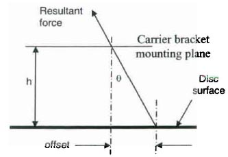
Figure 5 - Sprag angle coincides with angle between line of resultant force and intersect between centerline of piston and carrier bracket mounting plane.
Analysis of this variable offset and the sprag angle (friction angle), shows that the offset coincides approximately with the line of resultant force between the induced center of pressure and the intersection between the piston centerline at the carrier mounting plane as indicated in Figures 4 and 5.
In this instance interface coefficient of friction (3) was around 0.7. - thus when offset = 12mm then h = 12/0.7 = 17.1mm and and when offset = 15mm then h = 15/0.7 = 21.4mm.
The distance "h" for this brake was 19mm.
Test Rig Validation - This relation between sprag angle and observation center of pressure (as determined by pad wear) was evaluated against a commercial disc brake as indicated in Figure 6. The coefficient of friction, μ, for these tests is quoted by the brake manufacturers as 0.34.
The distance from the disc face to the caliper mounting bracket face is 37.5mm. This is mounted to an adaptor 26mm thick as shown in Figure 7.
The total distance from the disc to the adaptor mounting face being 37.5 + 26 = 63.5mm.
To determine the centre of pressure wear measurements were made on the pads, these being shown in Figure 8, the pad in Figure 9.
The centre of wear (pressure) or offset = 23mm

This observation on a completely different disc arrangement goes some way to support the spragging theory.

Figure 6 - Side view of commercial disc brake and relevant dimensions.

Figure 7 - General view of commercial disc brake showing ' mounting bracket.

Figure 8 - Wear pattem on surface of pad indicates centres of pressure.

Figure 9 - General view of pad. Note grooves evident on wear pattern.
On-vehicle validation - Noise was an issue following the release of a limited numbers of high performance versions of a high volume commercial "sports" type car. A trailing center of pressure was induced by the introduction of a 10mm chamfer on the leading edge of pad, the results as indicated in Table 2.
When the chamfer reduced to 6mm, through natural wear, the noise returned but when the chamfer of 10mm was re-established the noise was again eradicated.

Table 2 - Results of inducing trailing center of pressure by leading edge chamfer.
It wi" be noted that the original pad angle corresponds to the free mode antinode angular pitch for a 4-diametral mode order. As such the brake would be more likely to generate noise with this mode order. The introduction of the chamfer introduces 2 changes, that of a trailing centre of pressure but also the disc/pad interface geometry is altered. Regardless the effects of inducing a trailing centre of pressure is, to some degree, an indication that such a design parameter may be considered at the design stage.
MEASUREMENT OF CENTER OF PRESSURE DURING BRAKING
Although the static pressure distribution may be calculated, and measured (pressure sensitive films), there is little information regarding its calculated or measured position during a dynamic braking event. The unique method employed in this investigation allows the dynamic center of pressure to be measured during a normal noisy brake application.
Measurement of the dynamic center of pressure during braking is difficult. The unique technique was to use an embedded pressure sensitive film within the pad. To allow th s the film was first bonded to a smoolh pressure plate as shown in Figure 10.

Figure 10 - Pressure sensitive film bonded to metal support plate.

Figure 11 - Recessed pad and associated "plug".

Figure 12 - Pad assembly with film laminate sandwiched within pad.
A pad was prepared to receive the laminate by machining a recess and "plug" as shown in Figure 11. The film laminate was then fitted to the recess and the "plug" used to form a sandwich of the film laminate as shown in Figure 12. The pad was machined to give a level rubbing surface and the assembly used to measure the dynamic center of pressure on a test rig as shown in Figure 13.
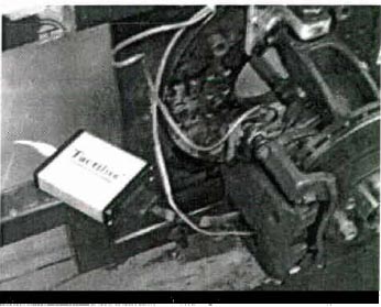
Figure 13 - Test rig using pressure sensitive pad.
ANALYSIS AND RESULTS
ANALYSIS
In a practical situation there will be an interaction between frictional effects (forces) at the pad abutment/caliper interface with the geometric features of the brake pad when it is in equilibrium. A measure of the relationships involved for the different types of abutment may be established and compared if it is assumed that the various forces acting on the pad are coplanar as shown in the brake caliper in Figure 14 and the freebody diagrams of the abutment arrangement in Figure 15.

Figure 14 - Co-planar forces added to piston pad. Position of reaction "R" (centre of pressure) to provide equilibrium depends on direction and magnitude of abutment force which in tum is dependant of friction level of friction material (μ) and friction level at abutment interface (μ2).
The force at the abutment face must equal the frictional force (μR) if the horizontal reaction at the pistonlbackplate interface is neglected.

Figure 15 - Free body diagram of trailing abutment pad
If the pad end tends to move in a vertical plane it will have a resistive force equal to the friction force x friction coefficient between pad and carrier finger (μ2). This vertical force (μ, μ2, R) will change direction as the pad end reverses direction.
In this case the system is not balanced and hence *N* is not equal to *R* and the relationship between the two may be determined by resolving forces vertically to give:

Furthermore by taking moments about the abutment, equilibrium will be attained if:

as μ2 => 0 then b => a + μt giving a maximum leading offset where 5mm is piston offset.
Given μ = 0.45, a = 63.49mm, t = 18.15 mm then the above becomes: b = 71.66 ± 28.57 μ2
Consider the condition when "b" is a maximum, i.e. a leading center of pressure: b = 71.66 + 28.57 μ2
From known pad friction level and known h = 23.18mm (in Figure 5)
Sprag angle = Tan α = μ = offset / 23.18 = 0.45 (given)
To sprag this gives leading offset = 10.43 mm
Offset = b - a - d (5mm piston offset)
Or Offset =71.66+ 28.57 μ2 - 63.49 - 5
Offset =3.17 + 28.57 μ2
giving μ2 = 0.254 maximum if offset = 10.43mm
This is a realistic value for the pad/abutment finger interface friction coefficient.
A stability envelope may be plotted for the varying characteristics as shown in Figure 16. This indicates a low μ2 would tend towards a more stable system.

Figure 16 - Plotted stability envelope for varying parameters, μ, μ2 & piston offset, d. In this instance the piston offset is Smm trailing (positive).
If this situation of a moving center of pressure is accepted then it may be related back to caliper mounting as follows. Consider Figures 17a-c showing the carrier/caliper mounting. The disc is moving left to right and the co-planar forces are indicated.

Figure 17 - Free body diagram of pad and carrier/caliper mounting plane with varying abutments force directions.
In Figure 17a the center of pressure is leading and as such the resultant force causes the mounting to rotate clockwise. If the center of pressure is less leading then the resulting force causes the mounting to rotate counter-clockwise as indicated in Figure 17b. Clearly if the center of pressure "hunts" between these two extremes it will pass a point where the resultant will cause the mounting to physically move axially (vertical in diagram) as shown in Figure 17c - spragging at its worst. In this case the normal force at the disc/pad interlace will increase because of the increased stiffness of the mounting and as such the disc will experience a variable and periodical out-of-plane excitation force. It is suggested this could be the source of noise generation.
MEASURED RESULTS
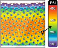
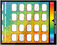
The results are dynamic and as a result the center of pressure moves constantly as the pad wears and as the pressure varies, Figure 18.

Figure 18 - Typical pressure distribution during braking. Note the higher pressures being at the outer edge of the leading side and generally central on the trailing side.

Figure 19 - Plots of center of pressure during braking under variable braking pressures.

Figure 20 - Instability diagram indicating variation in envelope for different pad abutment friction levels (μ2). Maximum and minimum leading/trailing centers of pressure obtained from Figure 19 at the assumed abutment friction level μ2 of 0.3 and pad friction level J.1 of 0.45. Other envelopes for μ = 0.35 and 0.55 are included to indicate sensitivity of instability to varying friction levels.
DISCUSSION OF RESULTS
Figure 19 shows the trace (or movement) of the centerof- pressure as brake pressure is varied. The vertical axis represents the offset with, in this case, the piston offset trailing by +5mm. Even with this trailing (positive) piston offset it can be seen that the center of pressure tends to be leading the piston and the majority leading the center of the pad. In addition it must be noted that low brake pressure levels leads to greater leading center of pressure and greater instability. The pressure is hardly ever transmitted on the trailing side of piston center. This Is generally what is experienced on a vehicle - noise most prevalent as brake pressure is reduced. During pressure application, the center of pressure moves between -11 ,1 mm and +6,3 mm as shown in Figure 19. This benchmark may be used to plot an instability diagram as shown in Figure 20 with an assumed μ2 = 0.3 and known pad friction level of 0.45. Additional envelopes for pad friction 0.35 and 0.45 are included to indicate sensitivity to friction level changes. It generally stays in the "spragging instability" area and as a consequence the brake generates noise. The spragging instability area for (μ ; μ2) = (0,45 ; 0,3) gives 3 between -13,3 mm and +6,2 mm. Measured tangential pressure centroid seems to let the system stay in the spragging instability region (based on static model).
CONCLUSIONS
The theoretical approach indicates why the caliper mounting geometry is important. Both rig and vehicle testing demonstrates that a trailing center of pressure will tend towards a stable, quiet brake and a leading center of pressure will result in the brake having a higher propensity to generate noise.
Even if the piston has an offset, trailing, piston the tendency towards a leading center of pressure persists, resulting in continued noise.
To ensure a leading center of pressure is not established on an existing brake it may be necessary to introduce a stepped shim at the piston/pad interface.
A mechanical instability that is not influenced by temperature or pressure fluctuations is possible within a brake system.
Such a mechanical instability is caused by "spragging" of the system, which would encourage low frequency noise generation.
Pad abutment is important, with a trailing abutment being found to be the most stable arrangement.
The co-planar forces acting on the pad tend to promote a leading offset. At minimum friction for the pad/caliper abutment interface the offset tends towards the critical offset value.
To promote stability a disc brake requires a low friction coefficient between pad abutment and caliper mounting bracket and a low friction material coefficient.
The position of the mounting plane for the caliper carrier bracket is important because of its influence over the spragging angle. It needs to be as close to the plane of the disc-rubbing surface as possible.
Measurements of the pad wear patterns of a commercial siding fist type caliper show the finger pad to have an opposite wear pattern to the piston pad. It is suggested that this may be due to the caliper twisting as a result of the spragging action.
CONCLUSIONS
The investigation of the centre of pressure and its influence on the propensity of a brake to generate noise is currently being extended with the modification of a 12- piston opposed caliper (6 per side - 3 outer radius and 3 inner). Inter-cylinder ports within the caliper body are sealed to allow individual pressure control of 4 piston sets. Leading and trailing pair and 2 middle individual pistons. The modifications allow the centre of pressure to be controlled both radially and along the length of the pad, inducing a leading or trailing centre of pressure as desired. Again static tests precede the dynamic measurements as a means to evaluate the criteria for noise is initiation.

Figure 21 - General test rig arrangement to control the pressure map of a 12 piston opposed type caliper (6 outboard and 6 in-board.
The basic arrangement showing the caliper, and 4 master cylinders controlling the pressure map are shown in Figure 21 and the pressure gauges and control panel in Figure 22. The Initial results shown noise may be readily generated with a leading center of pressure and noise propensity reduced with a trailing center of pressure.

Figure 22 - Pressure adjusters and gauges to adjust the overall center of pressure.
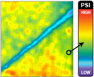
A typical static pressure map is shown in Figure 23. The central inner piston has most effect (most sensitive) to giving a uniform pressure distribution.
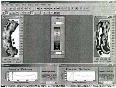
Figure 23 - Typical static pressure results. The map may be changed by altering the pressure provided by the 4 master cylinders (Figure 22).
Additionally Finite lement (FE) modeling and Contact analysis will make use of the collective data and embraced the measured data in vibration analysis and noise prediction.
ACKNOWLEDGMENTS
The authors would like to thank Bosch Braking Systems for their permission to release and publish this material and for providing much of the experimental data.
NOMENCLATURE
N = the force exerted by the piston.R = reaction between pad and disc
J.L = coefficient of friction at disc/pad interface
μ2 = coefficient of friction at pad/caliper or carrier bracket finger abutment interface. t = pad thickness (18.15mm)
a = pad abutment to center of piston (63.49mm)
b = pad abutment to center of disc/pad reaction force, "R".
c = distance from abutment to centre of pad (68.49).
d = Piston offset (5mm).
h = distance from disc surface to caliper mounting plane. REFERENCES
- Fieldhouse J.D. and Newcomb T.P. "The Techniques of Double Pulsed Holographic Interferometry Applied to the Problems of Noisy Disc brakes" - Vibration and Noise '95 pp 453-457. An international conference on vibration and noise. April 1995, Venice, Italy.
- Spurr R.T. "Brake Squeal" Paper No. C95n1, Symposium on Vibration and Noise in Motor Vehicles, IMechE 1971 pp 13-16.
- Fieldhouse JD "A Study of the Interface Pressure Distribution Between Pad and Rotor, the Coefficient of Friction and Caliper Mounting Geometry with Regard to Brake Noise" Brakes 2000 International Conference on Automotive Braking. Leeds July 10 - 12 2000 ISBN: 1-86058-261-3, pp3 - 18.Published by Mechanical Engineering Publications limited (MEP)
- liles, G. "An analysis of disc brake squeal using finite element methods.· SAE Paper No. 891150, 1989.
