


Article: Iron & Seal Society
New Technique for Ensuring Proper Forming Processes and Validation in Steel Pipe Production

Figure 1: The HSS is shown as it exit a the Turkshead stand
Until recently, measuring precise tolerances and efficacy of two mating surfaces under tension was difficult. Conventional strain gauges and load cells are usually too invasive or time intensive and costly to implement. With the advent of tactile pressure sensor film (TPSF) technology, a viable and economic metrology technique now exists for evaluating seal interfaces. Using the TPSF technique of force and pressure measurement not only sheds light on interfacial problems, but also confirms predictions generated by computer models, such as finite element analysis (FEA). Mechanical engineers and technicians need no longer incur the iterative process of trial and error to achieve product optimization. In general, any situation in which two components either contact or impact in a normal (perpendicular) fashion is a viable application to use the TPSF technique. In addition to simple visual inspection of the TPSF, the engineer also has the option of taking the evaluation one step further by applying one of the various post-process Interpretative systems described later in this article. (The specific TPSF analyzed in this article is known as Pressurex®)
A Case Study
 |
 |
|
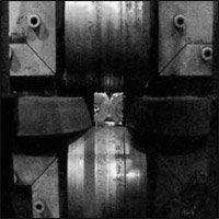
Figure 2: These are the rolls that perform final sizing of HSS products |
Figure 3: The edges of the ERW product mentioned in the article are forged together using weld rolls |
Prudential Steel Ltd., located in one of the western Canadian provinces, needed to determine the amount of force its forming roll bearings were being exposed to during the manufacture of ERW steel pipe. (Figure 1 shows an example of a finished product.) Both contact pressure magnitude and force distribution information needed to be determined. The company also wanted to ensure that successive stands in the forming process of the steel pipe were performing the proper amount of work or reduction. Its ERW steel pipe was of differing material gauges (from 0.250 to 0.500 inch wall) and grades, as well as different pipe diameters (4.5 to 10.75 inches). Prudential investigated the possible use of traditional load cells but found them to be cost prohibitive. An alternative solution available was the Pressurex TPSF from Sensor Products Inc.
Prudential cut the TPSF into 12 pieces, each having a dimension of 8 inches x 4 inches per piece. A series of experiments were then performed by attaching the TPSF with adhesive heat tape between the pipe surface and the roller bearings. Various roller bearing configurations, illustrated in both Figures 2 and 3. were used for the various HRW steel pipe diameters. For each test, a piece of TPSF was employed to capture total force distribution and magnitude. Additionally, when analyzed with an optical imaging system, TPSF is able to threshold an image to determine precisely how much contact area resides above and below certain parameters.
Through use of the film, Prudential successfully changed its bearing configurations to deal with higher pressures. This ultimately led to modifications in setup procedures for its operators and maintenance procedures for the roller bearings. Prudential saw the TPSF as validating its existing pressure ranges and tolerances in the forming of its ERW pipe.
Specifications of TPSF

Figure 4: A cross-section view of a piece of tactile pressure film reveling the special technology behind its efficient and inexpensive use
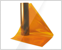
TPSF comes in the form of thin sheets, physically similar in appearance to a typical magaxine page or sheet of paper. These sheets range in thickness from 0.1016 to 0.2032 mm and are structurally affixed to a Mylar substrate for stiffness. While insuring stiffness, the Mylar substrate is pliable enough for the film to fit between intricate and curvaceous surfaces. The films come in various pressure sensitivities, ranging from 28 to 18,500 psi (2 to 1,300 kg/cm²). An engineer first needs to calculate the approximate amount of pressure loading at the interfacial surface before selecting the appropriate film range to use. Film ranges are purposefully kept within precise limits to maximize accuracy of pressure mapping information. If the ranges were wider, the levels of graduation of color intensity would be so tightly spaced along the color spectrum this pressure variation might be indistinguishable.
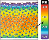
Pressurex® TPSF is a single use system, similar to Polaroid photo film, capturing a snapshot of maximal pressure loading at a specific moment in time. What the TPSF reveals is a very high resolution image of both pressure distribution and pressure magnitude. The way the film works is quite simple. Microcapsules embedded in the film rupture at precise pressure levels, causing them to release chemical contents that interact with a developer component, producing a visible color change (Figure 4). This quantifiable color change is directly proportional to the amount of pressure applied. The user is able to visually inspect the film for significant variations aberration and general uniformity Spatial resolution of the TPSF system is .005 to .015 mm, yielding ultra high definition imagery of force profile. The color change of the film is both instantaneous and permanent, enabling the film to be both immediately analyzed and then saved for archival purposes.
Use and Interpretation of TPSF
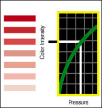
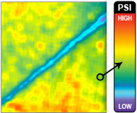
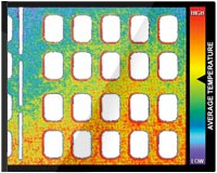
Figure 5: Similar to litmus paper, tactile pressure sensor film offers visual interpretation by using color intensity as a measure of pressure. Greater color intensity indicates a greater measurement of pressure values
Once a compressive load has been applied, the TPSF can now be analyzed in several different ways. The quickest and most economic technique is by visual comparison to a color calibration chart (conceptually similar to using litmus paper), as seen in Figure 5. The engineer can match the film's resultant color to this calibration table to obtain an approximate indication of pressure magnitude. Voids, pits, microcracks, warping and surface aberrations are immediately apparent upon visual inspection. Typically the visual interpretation method yields accuracy of ±15 percent hill-scale (kg/cm²).
For applications or situations in which shearing or tangential stresses are occurring between interfacial surfaces, a little ingenuity is required. Small pieces of the sensor film can be applied selectively at the points of greatest concern, preventing the smudging and crinkling (noise) of the TPSF that might occur from sideways shifting.
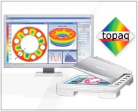
A more sophisticated and accurate technique of analysis and interpretation is by using an optical imaging tool. One such pressure analysis system, known as Topaq® consists of Windows-based software and a specially calibrated scanner system that reads and interprets the film. Images rendered by the Topaq® system are accurate to ±2 to 3 percent full-scale and are accompanied by a wealth of statistical data about the interface.
Key features of Topaq® include the ability to produce histogramic data of the image being analy/ed. Topaq not only allows for the analysis of the entire interfacial surface, but small and problematic areas can also be enlarged and enhanced and carefully scrutinized.
Conclusion
The TPSF technique, where implemented, has generally resulted in a positive return on investment. With relative ease, the two fundamental attributes of force distribution, namely total force and average kg/cm, can be visually assessed. A technician can be trained in the TPSF technique in a matter of hours. Data collected from using this technique has lie-come a powerful component in the information arsenal of several OK Ms involved within the steel industries worldwide. As a result of using the TPSF technique, manufacturers are able to assess optimal forces for consistent production of their steel products, as well as ensure proper maintenance procedures.
The TPSF technique takes steel and steel product producers a step closer to full-process standardization. The TPSF and optical analysis system have become powerful tools in the arsenals of fastener labs and customer research and development facilities. Using the TPSF in conjunction with Topaq® lends a high degree of statistical validation to interfacial analysis.