Dwyer-Joyce, R.S.1, Yao, C. 1, Zhang, J. 2, Lewis, R. 1, Drinkwater, B.W. 2
1Department of Mechanical Engineering,
University of Sheffield,
Mappin Street,
Sheffield, S1 3JD.
2Department of Mechanical Engineering,
University of Bristol,
University Walk,
Bristol, BS8 1TR.
Keywords: wheel-rail contact, ultrasound, measurement of contact area, ultrasonic array
Abstract
Failure of a wheel-rail contact is usually by wear or fatigue of either component. Both mechanisms depend on the state of stress which in turn depends on size and location of the contact patch. In this work the feasibility of an ultrasonic approach for measuring the contact, real time on a rail, has been evaluated. The approach is based on the physical phenomenon of ultrasonic reflection at an interface. If the wheel and rail surfaces make contact and are under high stress they will transmit an ultrasonic pulse. However, if there is no contact or the contact is under low stress then the wave is completely or partially reflected. By measuring the proportion of the wave reflected it is possible to deduce the extent of the contact area and also estimate the pressure distribution. In previous work [1] static wheel-rail contacts were scanned using a transducer to build up a two-dimensional (2D) map of the contact. The procedure was time consuming and could in no way be used for measurements on-line.
In this paper a method is presented that could be used at line speeds and so provide wheel-rail contact measurements in field trials. The scan is achieved by using an array transducer that performs a one dimensional electronic line scan. This, coupled with the speed of travel of the contact patch past the sensor location, enables a 2D map of the contact to be produced.
Specimens were cut from wheel and rail sections and loaded together hydraulically in a biaxial frame. An array transducer was mounted beneath the rail specimen. The array transducer consisted of 64 ultrasonic elements that could be pulsed independently, simultaneously, or with controlled phase difference. The signals were reflected back from the contact to effectively produce a line scan. The transducer was physically moved, to simulate the translation of the contact patch and so generate a series of 2D reflection profiles.
Contacts under a range of normal and lateral loads have been measured and compared with some simple results using pressure sensitive film. Whilst the map produced by 2 ultrasonic reflection is relatively coarse, the results agree well with measurements from the pressure sensitive film. The paper concludes with a discussion of how this array measurement procedure might be implemented at full line speed and what resolution could potentially be achieved.
Introduction
The wear and fatigue of railway wheels and rails depends on the contact conditions between the two bodies. Both the location of the contact region and its dimensions will affect the level of contract stress, this coupled with the path history is a major factor in determining the fatigue and wear performance. This in turn defines the maintenance and wheel or rail re-grinding intervals.
There are a number of analytical and computer based numerical models for predicting wheel-rail contact (see for example [2-6]) and the industry relies heavily on such predictions. However, there is currently no definitive experimental technique for determining the size and stress distribution within a wheel-rail contact in the field.
One method that shows promise is the use of ultrasonic reflection. When an ultrasonic wave strikes an interface between the wheel and rail it is partially reflected and partially transmitted. This is because the wheel and rail surfaces are rough to an extent and the interface consists of asperity contact regions and air gaps. A single ultrasonic transducer can give a point measurement of reflection (amplitude and phase) and hence degree of contact. If the transducer is scanned back and forth across the interface area then a 2D map of the reflection from the contact can be created. The greater the contact pressure on a region of the contact then the more conformal will be the surfaces. This means the ultrasonic reflection amplitude will be lower. Hence regions of low reflection correspond to regions of high pressure. References [1, 7-10] describe procedures, both analytical and empirical by which a relationship between reflection and contact pressure can be deduced.
Figure 1 shows the results of the approach (data from reference [1]) on specimens of un-used wheel and rail at a range of normal loads. Wheel and rail specimens have been pressed together and a transducer scanned in such a way as to record the reflection of ultrasound from the interface. The Hertz solution is marked as a white ellipse in each load case. A similar approach has also been carried out by Pau and coworkers [11-13].
![Fig. 1. Contact pressure maps measured by scanning an ultrasonic transducer across the contact for a range of normal loads (data from [1]).](https://www.sensorprod.com/wp-content/uploads/2023/08/image01-15.jpg.webp)
Fig. 1. Contact pressure maps measured by scanning an ultrasonic transducer
across the contact for a range of normal loads (data from [1]).
The method is effective, but the scanning process is time consuming (typically taking 30 minutes to measure a single contact region) and requires a bulky scanning frame to accurately locate the transducer. Clearly this is not suitable for anything but static measurements on laboratory based specimens.
In this work the feasibility of an alternative method is investigated. Rather than using a single ultrasonic transducer, a linear ultrasonic array transducer is arranged in the transverse direction beneath the contact. This fires a line of transducers simultaneously, or indeed in any pre-defined sequence, and records the reflection from each on separate measurement channels. In this way a line scan of the contact in the transverse direction is recorded. The motion of the contact patch with respect to the sensor location then provides the scanning in the rolling direction.
This approach has been evaluated on laboratory based specimens, where the contact patch motion is reproduced simply by moving the lateral position of the array transducer.
Background
Ultrasonic Array Transducers
An ultrasonic array transducer consists of a series of individual piezoelectric elements assembled in a single housing. Each element can be used to pulse and receive independently. Figure 2 schematically shows a linear ultrasonic array transducer that enables imaging in the x-z plane to be performed. Note that each array element i
s small in the x-direction and so outputs circular wave-fronts as shown. If all the transducers are pulsed simultaneously the individual sources combine and a plane wave front is generated (Fig. 2a). The transducers may be pulsed simultaneously in this way or by using delay circuitry, a pre-specified phase delay can be introduced between elements. The possibility of introducing a delay between pulsing operations allows the generation of a range of bespoke wave fronts. This process is known as beam-forming.
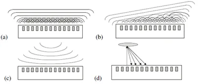
Fig. 2. Schematic diagram of an array transducer and beam-forming operations (a) a planar
wave front, (b) and angled wave front, (c) a focusing wave, and (d) pulsing and receiving
on each element in turn.
By applying a linear delay a plane wave can be generated at some angle, Ф (Fig. 2b). An angular sweep then consists of repeating this operation over a range of angles. In this way an object can be inspected from a range of angles. Another alternative (Fig. 4 2c) is to generate a focussing wave. The most comprehensive approach to array imaging is to pulse each transducer in turn whilst receiving in all others (Fig. 2d). The full time domain wave form is stored for each operation. In this way a full matrix (shown schematically in Fig. 3) is obtained.
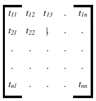
Fig. 3. Schematic of the pulse and receive matrix (tij represents the time domain
signal received on transducer j from the emitted pulse from transducer i).
Thus tij represents the time domain signal (a plot of amplitude against time) received on transducer j from the emitted pulse from transducer i. Once this matrix of data has been captured, all the beam forming operations described above can be performed as post-processing operations in software [14]. In the experiments that follow this approach has been used and a full matrix of data gathered for each load case.
Clearly the process of full-matrix-capture can be time consuming. Each transducer must be pulsed in sequence, data captured on all other transducers digitalised and stored. In practice instrumentation is used that incorporates a pulsing and receiving circuit from each of the elements to permit relatively rapid data capture.
For a planar interface, such as the wheel-rail contact, only the diagonal elements of the full-matrix are needed [t11, t22,… tnn]. In this way each element records a reflection measurement from a small region of the interface directly below its location [15]. However, though this requires less data, in terms of speed it is identical to fullmatrix capture as the number of firings per image remains the same (and equal to the number of array elements). This is equivalent to pulsing on transducer 1 and receiving on 1 whilst neglecting all other received signals on 2, 3 etc. This is called here the direct pulse-echo method.
Application to Wheel-Rail Contact
A typical pulse repetition frequency for a single transducer is 20 kHz; then each element receives a voltage pulse at 50 µs intervals. Therefore, to pulse through an array of 64 transducers in turn would take 3.2 ms. In this time a train travelling at 120 km/h will have moved 11 cm. So whilst the first element may capture an image reflected from the contact patch, subsequent elements will not. Clearly for dynamic measurements it is not feasible to pulse sequentially on each transducer element.
An alternative imaging strategy, termed the common source method, is to pulse all the elements simultaneously and record the individual signals received on all elements. This requires the equivalent of only one row of the matrix shown in Fig. 3 to be captured, which is a significantly faster operation than capture of the full-matrix of data. However, this approach generally leads to a more blurred image, when compared to imaging using the full-matrix of data [16].
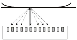
Fig. 4. An array transducer configured to measure a wheel-rail contact.
Since the contact is almost planar the non-normal reflections are small and neglected.
The wheel-rail contact occurs almost on a single plane that can be arranged to be parallel to the transducer. Figure 4 schematically shows the measurement principle. Since the interface is almost parallel to the pulse most of the image is reflected directly back to the pulsing element. The obliquely reflected signals are small. In other words, when pulsing a transducer only the signal tnn is strong whilst tm1, tm2 …. tmn are weak and can be neglected. Essentially the matrix shown in Fig. 4 is the diagonally dominant.
This approach will work well over the region of contact over the rail head. However when a flange contact is being observed because the plane of reflection is not parallel to the transducer, a larger proportion will be reflected obliquely and not be recorded by the transducer element. Pulsing and receiving on individual elements in this way would not give clear picture of the flange contact, since the signal from element 1 would not be received by element 1 but by, for example, elements 3 or 4 (i.e. the matrix in Fig. 3 would be diagonally weak). In order to measure the flange contact the full matrix of data would have to be recorded.
If common source imaging is performed using a pulse repetition frequency of 20 kHz the required data can be recorded at 0.05 ms intervals. For a train travelling at 120 km/h, then the measurement can be recorded for every 1.7 mm of train motion or a contact patch would be measured approximately 7 times as the wheel passes over the transducer location. The measurement frequency and relationship to image resolution is discussed in more detail in later.
In this work the common source imaging concept has been explored experimentally on a stationary wheel-rail contact but using pulse repetition frequencies sufficiently high to demonstrate that this approach could potentially be applied to a dynamic wheel-rail contact.
Ultrasonic Reflection at an Interface
The transmission and reflection of ultrasonic waves in a component or structure is a common tool for non-destructive testing. An ultrasonic pulse, incident on an interface between two materials, is partially reflected. The proportion of the displacement amplitude of the incident wave reflected depends on the acoustic mismatch between the two materials according to the relationship [17]:

Where R is the proportion of the wave reflected, (or the reflection coefficient) and z1 and z2 are the acoustic impedances (the product of wave speed, c and density, p) of the materials either side of the interface.
The acoustic impedances of steel and air are approximately zsteel = 45×106 kg/m2s, zair = 400 kg/m2s. Thus a wave will pass through an interface between two pieces of steel pressed together in
complete contact, but will be almost fully reflected at a steel-air interface.
Equation (1) only applies to perfect contact between the two materials. When a wheel rolls across a rail contact occurs only at the peak of the surface asperities. So within a nominal region over which contact occurs there are areas of asperity contact and air gaps.
The response of an incomplete interface to an ultrasonic wave has been studied extensively to investigate crack closure effects, [18,19] and asperity contact [20-25]. The air gaps do not act as individual reflectors of the sound wave. Instead, provided the wavelength of the sound wave is large compared with the size of the air gaps, the interface acts like a distributed spring and the reflection is given by [20, 26].

Where w is the angular frequency of the wave, w = 2πf, and K is the stiffness per unit area of the interface. The presence of the interface is thus treated as a thin compliant layer of stiffness K, where the stiffness arises from the reduction in density caused by the presence of air gaps in the otherwise solid to solid contact. Equation (2) is known as the quasi-static spring model of ultrasonic reflection.
If the load pressing the two bodies together is high then the real area of contact is high and there are few air gaps. The interface is then stiff; a small increase in load does not cause the surfaces to approach much closer. Conversely when the surfaces are under a light load the degree of contact is low and the interface is low stiffness. In general, the stiffness varies from zero to infinity as the real area of contact varies from zero to 100%.
The stiffness, and hence the reflection coefficient from Eq. (2), thus varies with contact pressure. Measurement of the reflection coefficient can then give information about the degree of contact at an interface and hence the contact pressure. By scanning an ultrasonic transducer across an interface a map of reflection can be generated. This approach has been used to study contact pressure distribution in ball on flat contacts [9], press fits [8], bolted joints [10] and wheel-rail contacts [1].
Reflection from a Wheel-Rail Contact
In earlier work [1] sections cut from wheel and rail components were pressed together in a loading frame. An ultrasonic transducer was scanned across the interface. A water bath was constructed to couple an ultrasonic transducer to the rail specimen. A similar approach was taken by Pau et al [11-13] who also created reflection coefficient maps of a wheel-rail contact. The reflection coefficient recorded at each location was converted to interface stiffness. In this way, via an empirically derived stiffness-pressure calibration curve, a map of the contact pressure distribution was obtained. Figure 1 showed an example set of results obtained by this approach.
Clearly the scanning process is time consuming and the water bath difficult to set up. It would not be feasible to carry out scanning like this on a dynamic contact. In this work the same physical principle of ultrasonic reflection was used but with an array transducer to permit for the first time measurements from a dynamic contact.
Apparatus & Experimental Procedure
Ultrasonic apparatus
Figure 5 shows a schematic diagram of the experimental apparatus. The instrumentation consisted of an ultrasonic array transducer, array pulse controller, data processing computer and wheel and rail test specimens.
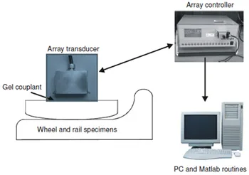
Fig. 5. Schematic diagram of the experimental apparatus.
The linear array transducer has 64 elements spaced at 0.63mm. The elements emit a broad band pulse of centre frequency 5 MHz consisting of 4 cycles. The total dimensions of this array were 57x 38 x 20 mm. This was driven by pulse controller (Peak NDT Micropulse 5PA). The controller generated voltage pulses to excite each transducer in a predefined sequence. The response from each transducer was then amplified and passed to the PC, where Matlab was used to capture, store and postprocess the data.
Hydraulic press and wheel-rail specimens
Specimens were cut from sections of used wheel and rail (Fig. 6a). The bottom face of the rail was cut to be as close as possible to be parallel to the contact face on the head of the rail. This was so that the ultrasonic beams would strike the interface normally and so be reflected back to the emitting transducer. The specimens were assembled in a purpose built loading frame (Fig. 6b). Hydraulic cylinders were used to apply load in the normal and tangential directions. The top plate of the loading frame had a hole cut into it. This allowed the array transducer to be coupled directly to the back face of the rail specimen. A water based gel couplant was used between the array transducer and rail specimen. The array transducer was positioned by hand in a range of positions and its location measured against a simple scale.
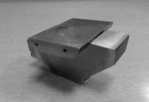
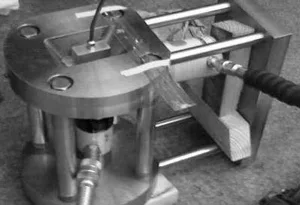
Fig. 6 Photographs of (a) the wheel and rail specimens and (b) the loading fram
showing the location of the ultrasonic transducer.
Loading procedure and signal processing
A sequence of normal loads, from 0 to 80 kN, and lateral loads from 0 to 9 kN were applied to the wheel-rail sample. The combination of normal and lateral load that could be used depends on the friction coefficient; it was found that for a normal load of 80 kN a maximum lateral load of 9 kN could be applied before the specimens started to slip. This loading regime represents typical loads that might be achieved on a passenger line vehicle.
For each load step full-matrix capture of the array data was performed. A set of results was also recorded when the specimens were unloaded and the wheel part removed in order to define a set of reference signals from a known steel air interface (i.e. virtually 100% reflection). All subsequent signals reflected from loaded interfaces were then divided by the corresponding steel-air reference signal. In this way the reflected voltage amplitude data is converted into reflection coefficient, R data.
A series of measurements was recorded with the transducer in several locations in both transverse and longitudinal orientations. Figure 7 schematically shows these positions and the co-ordinate system.
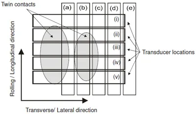
Fig. 7. Schematic diagram showing the transducer lateral (i to v) and longitudinal (a to e)
locations with respect to the wheel-rail contact regions.
Pressure Sensitive Film
As a preliminary to the ultrasonic tests, pressure sensitive film (Pressurex from Sensor Products Inc.) was used to establish the approximate contact area. The thin mylar based film contains micro-capsules of die that break under a specific contact pressure. When the film is pressed between two contacting surfaces an imprint is left where the intensity is proportional to the contact pressure.
The film was placed between the wheel and rail specimen that were then loaded to a pr
edefined end load. The film was then removed and a fresh piece inserted and loaded to a new end load. Figure 8 shows a sequence of imprints on the films for increasing loads.
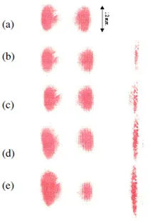
Fig. 8. Images from pressure sensitive film experiments for normal load P=80 kN
under different applied lateral forces, Q. (a) Q=0 kN, (b) Q=2 kN, (c) Q=4 kN, (d)
Q=6 kN, (e) Q=9 kN.
The images show three contact patches, two are from the contact between rail head and wheel tread, and the third from the flange-gauge contact. The wheel is slightly hollowed out and it is this that causes the double contact patch. As the lateral load is increased the flange makes contact with the rail gauge face and a third contact region appears.
Results
Direct Pulse Echo Experiments
Figure 9 shows a series of reflection coefficient profiles in the transverse plane running approximately through the centre of the contact (position (iii) in Fig. 8). In this case only the direct pulse-echo data [t11, t22,… tnn] is shown which corresponds to the diagonal of the full-matrix of data shown in Fig. 3. As the load is increased the surfaces are pushed together more closely and more of the sound wave passes through so the reflection coefficient reduces. Two distinct contact regions can be observed corresponding to the two contact patches seen in Fig. 8(a).
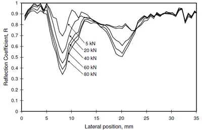
Fig. 9. Reflection coefficient profiles in the transverse direction across the contact
(recorded at position (iii) in Fig. 8) at the total load is increased from 5 to 80 kN.
Figure 10 shows a similar reflection coefficient profile, but this time in the longitudinal direction (location (b) in Fig. 7). One contact region is seen; there is some distortion to the right hand side of the region. It is not clear whether this is an artefact in the reflection data or this is some feature in the contact. The pressure sensitive film results also show a small feature towards the top right of the left hand patch. If this feature is due to surface damage it would also be expected to perturb the ultrasonic signals and so could have caused the ripple seen in the data.
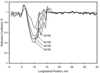
Fig. 10. Reflection coefficient profiles in the longitudinal direction across the
contact (recorded at position (b) in Fig. 8) at the total load is increased from 20 to 80 kN.
Assembling a Reflection Map
A series of measurements for positions (i) to (v) were recorded as the load was increased. Again the specimens were not disassembled during the loading sequence. The transducer was physically moved to each position during the load step. The idea here is to simulate the wheel passing over the rail and the array recording a series of snap-shots from the contact. The data has been assembled into reflection coefficient maps shown in Fig. 11 for scans in the lateral direction. The lighter colour shading shows areas of low reflection and therefore regions of more conformal contact. The process was repeated in the longitudinal direction (for the transducer positions (a) to (f)) and the data shown as Fig. 12.
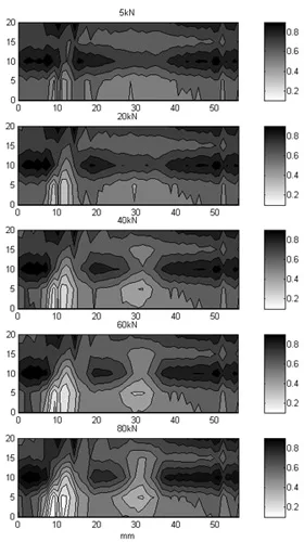
Fig. 11. A map of reflection coefficient obtained by assembling together five
reflection coefficient profiles in the lateral direction under normal loads of (top to bottom)
P=20 kN, P=40 kN, P=60 kN, and P=80 kN.
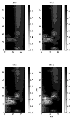
Fig. 12. A map of reflection coefficient obtained by assembling together five
reflection coefficient profiles in the longitudinal direction under normal loads of
(top) P=20 kN, and P=40 kN, (bottom) P=60 kN and P=80 kN.
The maps in Fig. 11 clearly show two contact patches and agree qualitatively with the pressure sensitive film results. The five lateral scans recorded have not quite captured the whole of the contact region, and further measurement locations below those shown would be needed to complete the picture. This could not be done since because the design of loading frame would not permit the transducer to be located in this position. The data of Fig. 12 is from the same specimens in the longitudinal direction. Only the smaller of the two contact patches has been captured, again the geometry of the loading frame was such that more data across the whole area could not be captured.
Comparison of Methods
Figure 13 shows four different sets of data plotted on the same scale. Figure 13a shows the pressure sensitive film results. Figure 13b is a map recorded using the method of [1] where a single transducer has been scanned across the contact. Figure 13c shows the array results (repeated from Fig. 11).
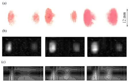
Fig. 13. Experimental and theoretical approaches for contact area measurement for
three normal loads 20 kN, 40 kN, and 80 kN plotted at the same scale. (a) Pressure
sensitive film, (b) scans of the contact using a single transducer, (c) scans of the
contact using an array transducer.
The three experimental approaches show qualitatively similar contact patch dimensions. Table 1 shows the semi-minor and semi-major radii of the measured contacts for each load (where the subscript signifies the contact patch number). These dimensions have been estimated by drawing the best fit ellipse to the data and recording the minor and major radii.
The pressure sensitive film will over-predict the contact region since it has a finite thickness. Both ultrasonic measurements will include some blurring due to the finite beam dimensions. This will also tend to enlarge the contact image slightly. It should be noted that direct comparison is not possible because it is not possible to exactly relocate the wheel and rail specimens between experiments.
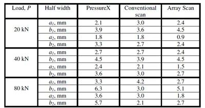
Table 1. Comparison of the semi-minor, a and semi-major radii, b of the contact
regions 1 and 2 measured by the experimental techniques.
Figure 14 shows a chart comparing the contact areas deduced by the three experimental methods. The data has been obtained by summing the areas for the two contact patches d
etermined in each loading case. Again it can be seen that the PressureX film gives a larger prediction that the two ultrasonic methods.
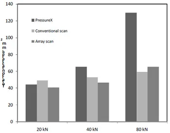
Fig. 14. Comparison of the total contact area determined by the three experimental methods.
Discussion
Accuracy and Repeatability
There are two issues for consideration concerning the accuracy and repeatability of the data. The first is whether the data is self consistent, the second is whether the data accurately measures the area of contact and contours.
One check of the self consistency of the results is whether the out of contact regions measured show a reflection coefficient of one throughout the loading. Clearly when out of contact the wave is reflected back from a steel-air interface and so the wave should be fully reflected. In Figs. 10 and 11 the reflection for the out of contact regions varies from 0.9 to 1. The fact that they are non-unity indicates that the reference has changed slightly. All signals are reflected signals are divided by the reflection from an unloaded specimen. During the reloading the transducer can shift slightly or the surfaces deflect so the reference no longer corresponds to exactly the same location. If the transducer were rigidly located, for example by adhesively bonding, it would remove most of this error. However it does mean for a non-bonded transducer, as used in these experiments there is approximately a 10% change in the signal during the loading.
When the specimens are disassembled and reloaded they will contact in a slightly different orientation. Guides were used to relocate them as closely as possible. But it is inevitable that the micro-scale asperity contacts will be different. It is therefore expected that when comparing across different loading tests (and for example the data of Fig. 13) there will be some discrepancy.
The measurement technique relies on the use of a relatively coarse spatial resolution transducer (of the order of 0.5 to 1mm). Using this equipment will be subject to this inherent inaccuracy. This means that the edges of a contact patch of say 5 x 2 mm could be blurred by 0.5 mm, resulting in over-predictions of as much as 50% on the shorter side. The results must be viewed bearing this in mind. Without improvements in the transducer resolution the results can only be compared qualitatively with theoretical contact models. However, the location of the contact patch, its fragmentation (i.e. into one or more regions) is very useful in comparing with theoretical predictions. The prediction of the contact patch under dynamic conditions is very difficult. This requires a two stage prediction process. Firstly the loading must be determined; this is usually obtained from multi-body dynamics models of the vehicle. The second is to use some form of contact model to predict contact are and pressure distribution from the applied loading. The latter are fairly well established modelling techniques [2 to 6] and probably this experimental data can do little to validate or improve these modelling procedures. However, there is scope for using this kind of experimental procedure in the field to interpret and validate multi-body dynamics models of the wheel-set and the resulting size and location of the contact patch. The output from models of this sort is highly dependent on input parameters such as vehicle element properties, track irregularity, contact element geometries, and friction coefficient. A means to measure the contact location and approximate dimensions would help with the refinement of the assumptions used in the models.
Practical Implementation
All the work described above was carried out on laboratory specimens in static contact. Extending this to field application, whilst technically feasible, would present 17 a significant challenge. A hole would need to be cut in the rail web and the transducer bonded to a reasonably smooth surface machined under the rail head. The thickness of rail material between the contact and the transducer should not pose a major problem for wave propagation. The ultrasonic wave would not be attenuated to any great extent (provided there were no large defects or cavities within the head material). Certainly transmission through 10 cm of steel would present no problem (rail is commonly inspected by similar ultrasonic techniques employing similar frequencies).
The rail head in the field is subject to contamination, particularly the presence of water or oil. A fluid film present in the interface between the wheel and rail will allow a greater transmission of ultrasound. It is likely that the film would be very thin, and the ultrasonic signal would still be dominated by the asperity contact effects. However this effect would need to be quantified, and an appropriate substitute for Eq. (2) implemented. Reference [27] describes a model that considers the ultrasonic reflection for a mixed regime interface consisting of both asperity contact and liquid contact. Perhaps the biggest challenge would simply to make the equipment robust enough to survive in a harsh outdoor environment subject to rough treatment, contamination, and temperature variation.
Train Velocity and the Rate of Data Capture
In this work the array provides one axis of measurement as the transducer elements all emit and receive in parallel. The second axis was obtained by physically indexing the transducer assembly. For application in the field the indexing would be caused by the motion of the wheel across the rail. The question arises as to how many lateral measurements could be recorded as the wheel passes over. Clearly this depends on the train speed, size of the contact region, and pulse repetition frequency of the array transducer. Figure 15 shows the relationship between the train speed, pulse repetition frequency, and the number of common source method array measurements that could be recorded.
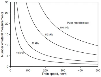
Fig. 15. The relationship between train speed, pulse repetition rate, and the number of
lateral measurements that could be recorded.
The repetition frequency is a function of the pulsing circuitry in the array controller. In this work 20 kHz was used. Pulsing faster than this is potentially possible but likely to involve expensive equipment. At this rate between 5 and 10 lateral measurements would appear to be possible, depending on train speed. Thus reflection maps of 64 x 5 for a typical contact could be expected. Such as system could either pulse continuously or be triggered by the approach of a train to capture a specific wheel-rail event. For example it would be feasible to record a single lateral measurement through the contact for each wheel on the vehicle.
Spatial Resolution
Each transducer element has a width of 0.53 mm. In the pulse-echo measurements (Figs. 9-12) the ultrasonic waves emitted by a given element are reflected from the interface and received by the same element. Although the ultrasonic waves spread out after leaving the element, only those that hit the interface at the appropriate angle (typically normal incidence) return to the element. This means that the measurement is essentially an aggregate of the reflection over a region of similar dimensions to the transducer element. The spatial resolution is thus relatively low, certainly not enough to pick out the detail of individual asperity contacts; but possibly enough to pick out contact variation caused by surface dents or defects
Post-Processing and the Total Focusing Method
The approach used to gener
ate Figs. 9 to 12 was to extract the pulse-echo signals from the full-matrix of data (shown in Fig. 3). This means that all data off the diagonal of the matrix shown in Fig. 3 is discarded. There are some other opportunities to use all the data that has been generated.
An alternative approach is to use the full-matrix of data to achieve a focus at every point across the wheel-rail interface. The image, I(x,z), is then formed by;

where xi and xj are the transducer locations on the x-axis. At each point in space (i.e. along the wheel-rail interface in this case) the parts of each time-domain signal that have travelled from a transmitter, to the imaging point, and back to a receiver, are summed. This is imaging technique is known as the total focusing method (TFM) and it has been shown to produce the best imaging resolution for a given array. Holmes et al. [14] used TFM to find the location of defects and describes the method in detail.
Figure 16 shows a comparison between the pulse-echo approach (i.e. the data of Fig. 9) with the TFM approach using the full-matrix data. Two loads cases are shown (Figs. 16a and b).
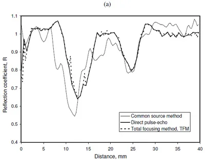
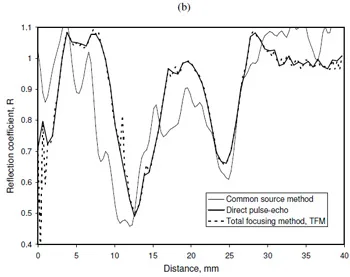
It is perhaps not surprising that the TFM plot is very similar to the pulse-echo plot. The wheel-rail contact is largely parallel to the array plane. This means that significant energy is reflected directly back to the emitting transducer. However, it should be noted that this would require the array elements to be pulsed individually. The pulsing frequency is then 20 kHz ÷ 64 which would be much too slow to measure a contact moving at train speed.
Another way of considering the data is to simulate what would happen if all the elements transmit and receive in parallel at the same time. This is termed the common source method. The data processed in this way is also shown on Fig. 16. This does show some difference between the two more accurate methods. This would mean that there would be significant cross talk between transducer elements. The mechanism is quite complex and at this stage it is difficult to quantify the likely error. However, this approach has the advantage that it would be very quick a line scan of the contact could be achieved in the time it takes to pulse one element. When the wheel rolls over the rail there would not be enough time to pulse each transducer independently. It is the simultaneous transmitting that is important to capture enough data should this method be applied in the field.
Conclusions
Ultrasonic reflection has been used in the past to measure wheel-rail contacts. However, this has been done by scanning a single transducer back and forth across the interface to build up a map. This study has explored the feasibility of using an ultrasonic array to achieve similar output. The array provided one dimension of the scan and physically moving the transducer to simulate wheel passage the other. Potentially this approach could be used track-side to obtain field data.
Specimens of wheel and rail were pressed together under a range of normal and lateral loads. The geometry of the surfaces was such that a double contact occurred between the rail head and wheel tread. Maps of ultrasonic reflection were generated by recording a series of array scans. These maps were qualitatively similar to those produced by scans of static contacts and measurements recorded with pressure sensitive film. The discretisation for a map recorded in this way would always be relatively coarse (of the order of 64 x 5 data points) and the spatial resolution would be low. So, whilst the results are not as detailed as those obtained from a scanning approach, useful data can still be achieved.
The repetition rate of a conventional pulsing system is such that the array of elements must all fire simultaneously. Results from the common source imaging method have been presented which show good correlation with the traditional (but slower) imaging techniques. This encouraging result suggests that a wheel-rail contact could be characterised rapidly on-line with a single firing. This work represents a first step toward developing a methodology for track side measurements but much additional work is necessary to achieve a practical implementation.
References
- Marshall, M.B., Lewis, R., Dwyer-Joyce, R.S., Olofsson, U., Bjorklund, S., 2006, “Experimental Characterisation of Wheel-Rail Contact Patch Evolution,” ASME J. Tribology, 128 (3), pp. 493-504.
- Kalker, J.J., 1982, “A Fast Algorithm For the Simplified Theory of Rolling Contact,” Vehicle System Dynamics, 11, pp. 1-13.
- Bower A. F., Johnson K. L., 1991, “Plastic Flow and Shakedown of the Rail Surface in Repeated Wheel-Rail Contact,” Wear, 144, pp. 1-18.
- Telliskivi, T., Olofsson U., 2001, “Contact Mechanics Analysis of Measured Wheel-Rail Profiles using the Finite Element Method,” Proc. IMechE Part F, Journal of Rail and Rapid Transit, 215, pp. 65-72.
- Yan, W., Fischer, F.D., 2000, “Applicability of the Hertz Contact Theory to Rail-Wheel Contact Problems,” Archives of Applied Mechanics, 70, pp. 255-268.
- Kapoor, A., Franklin, F. J., Wong, S. K. and Ishida, M., “Surface Roughness and Plastic Flow in Rail Wheel Contact,” 2002, Wear, 253, pp. 257-264.
- Dwyer-Joyce, R.S. and Drinkwater, B.W., 2004, “In-Situ Measurement of Contact Area and Pressure Distribution in Machine Elements,” Tribology Letters, 14(1), pp 41-52.
- Lewis, R., Marshall, M.B., and Dwyer-Joyce, R.S., 2005, “Measurement of Interface Pressure in Interference Fits,” Proc. IMechE Part C, 219(2), pp. 127-139.
- Hodgson, K., Dwyer-Joyce, R. S., and Drinkwater, B. W., 2000, “Ultrasound as an Experimental Tool for Investigating Engineering Contacts,” Proc. 9th Nordic Symposium on Tribology ‘Nordtrib 2000,’ 2, pp. 377-386.
- Marshall, M.B., Lewis, R., and Dwyer-Joyce, R.S., 2005, “Characterisation of Contact Pressure Distribution in Bolted Joints,” Strain, 42, pp. 31-43.
- Pau, M., Aymerich, F., Ginesu, F., 2000, “Ultrasonic Measurement of Nominal Contact Area and Contact Pressure in a Wheel/Rail System,” Proc. IMechE Part F, Journal of Rail and Rapid Transit, 214, pp231-243.
- Pau, M., Aymerich, F., Ginesu, F., 2001, “Measurements of Nominal Contact Area in Metallic Surfaces: A Comparison Between an Ultrasonic Method and a Pressure Sensitive Film,” Wear, 249, pp. 533-535.
- Pau, M., Aymerich, F., and Ginesu, F., 2002, “Distribution of Contact Pressure in Wheel–Rail Contact Area,” Wear, 253, pp. 265-274.
- Holmes, C., Drinkwater, B.W., and Wilcox, P., 2005, “Post-Processing of the Full Matrix of Ultrasonic Transmit-Receive Array Data for Non-Destructive Evaluation,” NDT & E International, 38, pp. 701-711.
- Zhang, J. and Drinkwater, B.W., 2008, “Thin Oil-film Thickness Distribution Measurement Using Ultrasonic Arrays,” NDT & E International, 41, pp. 596-601.
- Chiao, R.Y., Thomas, L.J., 1994, “Analytical Evaluation of Sampled aperture Ultrasonic Imaging Techniques for NDE,” IEEE Transactions on Ultrasonics, Ferroelectrics, and Frequency Control, 41, pp. 484-493.
- Kräutkramer, J. and Kräutkramer, H., 1975, Ultrasonic testing of materials, Springer-Verla
g, New York. - Haines, N. F., 1980, “The Theory of Sound Transmission and Reflection at Contacting Surfaces,” Report RD/B/N4744, CEGB Research Division, Berkeley Nuclear Laboratories.
- Buck, O., Thompson, R.B., and Rehbein, D.K., 1984, “The Interaction of Ultrasound with Contacting Asperities: Applications to Crack Closure and Fatigue Crack Growth,” J. of Nondestructive Evaluation, 4, pp. 203-212
- Kendall, K. and Tabor, D., 1971, “An Ultrasonic Study of the Area of Contact between Stationary and Sliding Surfaces,” Proc. R. Soc. Lond. A, 323, pp. 321-340.
- Krolikowski, J. and J. Szczepek, 1991, “Prediction of Contact Parameters using Ultrasonic Method,” Wear, 148, 181-195.
- Nagy, P.B., 1992, “Ultrasonic Classification of Imperfect Interfaces,” J. of Non-destructive Evaluation, 11, 127-139.
- Drinkwater, B. W., Dwyer-Joyce, R. S. and Cawley, P., 1996, “A Study of the Interaction between Ultrasound and a Partially Contacting Solid-Solid Interface,” Proc. R. Soc. Lond. A, 452, pp. 2613-2628.
- Dwyer-Joyce, R. S., Drinkwater, B. W., and Quinn, A.M., 2001, “The Use of Ultrasound in the Investigation of Rough Surface Interfaces,” ASME Journal of Tribology, 123, pp. 8-16.
- Baltazar, A., Rokhlin, S., and Pecorari, C., 2002, “On the Relationship between Ultrasonic and Micromechanical Properties of Contacting Rough Surfaces,” Journal of the Mechanics and Physics of Solids, 50, pp. 1397-1416.
- Tattersall, A.G., 1973, “The Ultrasonic Pulse-Echo Technique as Applied to Adhesion Testing,” J. Physics D: Applied Physics, 6, pp. 819-832.
- Gonzalez-Valadez, M., Dwyer-Joyce, R.S., & Lewis, R., 2004, “Ultrasonic Reflection from Mixed Liquid-Solid Contacts and the Determination of Interface Stiffness,” Proceedings of the 31st Leeds-Lyon Symposium on Tribology, Elsevier Tribology Series, 48, pp. 313-322.

