Samuel G. Paikowsky – Geotechnical Engineering Research Laboratory, University of Massachusetts, Lowell, MA 01854, USA
Lawrence E. Rolwes – Parson Corporation, Concord, NH 03301, USA
Hsienjen S. Tien – Geotech Engineering and Testing, Houston TX 77022-2908, USA
ABSTRACT
The arching phenomenon is manifested through the reduction of stresses experienced by underground structures. Arching plays an important role in engineering construction including; excavations, retaining structures, tunnel boring machines, culverts and underground facilities. The arching mechanism is intrinsic to granular material/rock mass independent of scale effect. It’s fundamental mechanism relates to the ability of discrete units to transfer loads through interaction in a preferable geometry and thus to bridge between the zone (or point) of load application to the zone (or points) of reaction. The testing results of two advanced experimental techniques are presented and analyzed. One utilizes a model of granular material made of photoelastic particles. The model and the sophisticated image and global data acquisition system allow to track the development of the arching within ideal granular material during a trap door experiment by following the motion of each particle and the contact forces between the particles. The second utilizes tactile sensor technology enabling to monitor the normal stresses at numerous points simultaneously. The aerial stress distribution during a trap door testing in sand is presented. The obtained information allows one to observe the changes associated the arching mechanism and the stress variation resulting from it.
1 PHOTOELEASTIC DISCRETE SIMULATION
De Josselin de Jong and Verruijt (1969) sug-gested that the interparticle contact force magnitude could be determined as a function of the rela-tive size of the isochromatic fringes at the contact, and the corresponding contact force direction fol-lowed a line connecting the center of gravity of isochromatic fringe near the contact. The isochromatic fringes can be observed through a circular polariscope, which consist of quarter-wave plates and polarizers. Further development and testing of the above method has been pre-sented by Paikowsky et. al. (1993). A calibration process establishing the relationship between the photoelastic isochromatic fringes and the contact force magnitude and direction were developed, allowing to accurately monitor the interparticle con-tact forces. Independent digital images acquired in parallel, enable to follow markings on the particles. These images allow the motion of each particle to be monitored, identifying both translation and rotation (Paikowsky and Xi, 2000). The two techniques were combined into an experimental system that enables the investigation of both, ki-nematic behavior and interparticle contact force variation of photoelastic particles. This experi-mental system was termed Photoelastic Discrete Simulation (PDS).
2 PHOTOELASTIC EXPERIMENT SETUP
The PDS was used to interpret trap door ex-periments using a granular mass made of photoe-lastic particles. A trap door testing system has been developed to study the arching behavior of particulate materials on the contact detail level. The system allows one to perform trap door tests under different side boundaries (e.g. smooth or rough side boundaries), loading conditions, trap door movement (active or passive), and to ac-commodate different sizes of trap doors. One-inch diameter photoelastic particles with different as-pect ratios (AR) were used (round AR=1, elliptical AR=1.25). The layout of the experimental system, and a flow chart describing the comprehensive image acquisition and analysis system is presented by Paikowsky and Xi (1997), and Tien and Pai-kowsky (2001).
A detailed depiction of the loading and trap door systems is presented in Figure 1. Experiment #9 of active arching included 882 25.4 mm diameter, 9.5 mm thick, round photoelastic particles. The sample size before loading was 792.2 mm (H) by 635 mm (W) (see Figure 1). The trap door size was 317.5 mm wide. Experiment #10 had the same setup as Experiment #9. The results of both tests are presented in comparison and separately as needed.
3 TEST RESULTS
3.1 Global Response
The global response of the tested sample was collected from six load cells located at the top, bottom, and two sides of the sample, and from two displacement transducers placed at the top and bottom (see Figure 1).
The global response testing results related to vertical loads and trap door displacements are pre-sented in Figure 2. The force acting on the trap door is presented in Figure 2-c. A constant load of 705.4 N acted on the door after the vertical seating load to the sample increased to 1550 N. The force on the door dropped to 0 N when the displacement of the trap door was approximately 1 mm. Since the trap door length is 317.5 mm, a displacement of 1 mm is only 0.3% of the trap door size. This ratio is similar to the former re-sults of trap door experiments that had the mini-mum force on the trap door with the door dis-placement under 1% of the trap door size (Ter-zaghi 1936, Tien 1996). The force on the trap door stayed close to 0 N till the trap door dis-placement reached 10 mm. At this point, the force started to increase, indicative of the unstable state of the particles forming the arch above the door.
3.2 Interparticle Behavior
Figure 3 presents the photoelastic images and the associated contact forces magnitude contours for frames #0 and #34 of experiment #9. These frames represent the state of the sample under seating vertical load before any movement (frame #0), and when no force is acting on the trap door as a result of a displacement of about 1mm (frame #34). A comparison between the trap door load cell measurements (figure 2), and the photoelastic interpretations (Figure 3) of the force acting on the door indicate on a difference of forces of 10.4% and 8.8% (load cell greater than photoelastic) for frames #0 and #34 respectively. Additional de-tails depicting the particle’s interparticle forces, displacements, and rotations are presented by Tien and Paikowsky (2001).
3.3 Load Distribution
Figures 4a and 4b present the forces developed between particles and between particles and the boundaries in Experiment #10 frames 22 and 49 respectively. Frames 22 and 49 refer to 30 sec-onds and 105 sec after the stationary conditions which correspond to a 0.52 mm and 1.80 mm movements of the trap door respectively. Frames 10 and 22 represent the intermediate and peak conditions of the arching. The data in Figure 4 suggests (i) the formation of chain forces around the yielding zone (trap door) and (ii) with con-tinuation of motion these forces transfer away from the yielding zone. Further details are beyond the available space of this pap
er.
4 TACTILE SENSOR MEASUREMENTS
Grid based tactile sensor technology enables to measure stresses at a large number of points in close proximity, thus allowing for a realistic nor-mal stress distribution. The sensors are made of two layers of polyester material and are about 0.3 mm thick. Consequently, the sensor can be viewed as non-intrusive with minimal effect of the measurement on the measured values. Initial ap-plications of the technology for Geotechnical en-gineering were presented by Paikowsky and Ha-jduk (1997) and Paikowsky et. al. (2000).
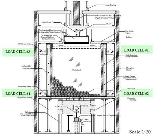
Figure 1. Testing Apparatus For the Trap Door Experiment Using Photoelastic Particles
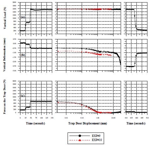
Figure 2. Sample Global Responses as a Function of Time and Trap Door Displacement (EXP #9 & 10) (a) Vertical Load (b) Vertical Deformation (c) Force on the Trap Door
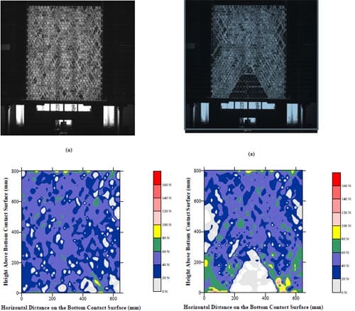
Figure 3 Interparticle Forces of EXP #9 Under Seating Load (left) and Full Arching Development (right) (Frames #0 and #34) Respectively. (a) Photoelastic Fringe Image and (b) Contact Force Magnitude Con-tours
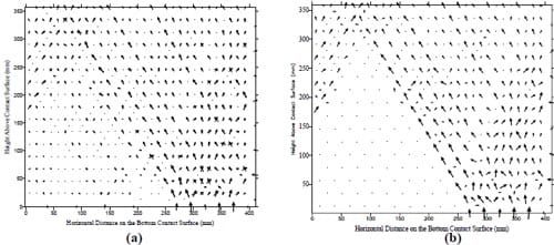
Figure 4 Vector Field of Interaction Forces (a) During and (b) Peak of Arch Development in Exp.#10
Figure 5a presents the schematic cross-section of a testing device measures 45.7 by 55.9 cm in area and 55.9 cm in height (measured from the trap door plane). A trap door 3.81cm wide and 45.7cm long was built as part of the base of the testing device. The trap door was equipped (cov-ered) with a 9801 type sensor comprised of 3 rows of 16 sensors each (48 sensors all together). Each sensel area is 6.35 x 7.87 mm. Two full-sized 9801 sensors (6 x 16 sensors each) were used in the apparatus, centered on both sides of the door. Two direct current displacement transducers (DCDT’s) and a load cell monitored the motion of the trap door and the total force acting on it, re-spectively. The apparatus was filled using sieve deposition of dry Ottawa sand (D50 = 0.5 mm, Cc = 1.08, Cu =1.43). Tests were conducted by displac-ing the trap door at an initial slow rate of ap-proximately 0.00254 mm/sec increasing (follow-ing the development of the full arching) to a rate of 0.0165 mm/sec. The slow rate allows continu-ous monitoring of the stress distribution over the trap door and the vicinity (in a movie format) and the monitoring of the relationship between the trap door movement and the stress field development. One image in the sequence of a trap door test (TD Test 5 Frame 2) is presented in Figure 5b in the form of a three dimensional stress distribution. An average cross section stress distribution. is pre-sented in Figure 5c. Figures 5b and 5c present the stage of 0.27mm door displacement and minimal load on the trap door (3.2N out of 87.1N).
The complete measurements referring to the global load-displacement relationship and the ae-rial stress distribution cannot be detailed in this paper. The observations suggest that the initial displacement of the trap door resulted in an in-crease in pressure that was isolated within narrow bands directly adjacent to either side of the door. These observations are consistent with the photoe-lastic testing results presented in Figure 4 and those obtained by Park (2001). With increased trap door displacement, the pressures within these bands were dispersed over the outer zones of the trap door.
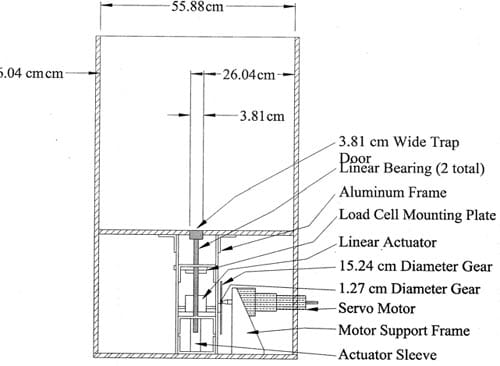
Figure 5a – Tactile Sensor Trap Door Testing Section through Experimental Apparatus
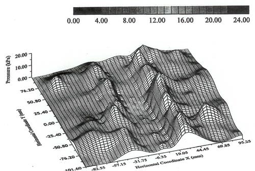
Figure 5b – Tactile Sensor Trap Door Testing 3-D Pressure Distribution Over and Around the Trap Door Distribution
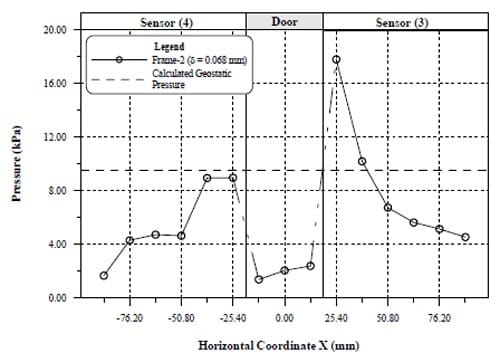
Figure 5c – Tactile Sensor Trap Door Testing Average Cross Section Pressure
REFERENCES
- De Josselin de Jong, G., Verruijt, A. (1969), “Etude Photo-Elastique d’un Empilement de Disques”. Cah. Gr. Franc. Rheol. Vol. 2, No. 73, pp. 73-86.
- Paikowsky, S.G., DiRocco K.J. and Xi F., (1993), “Interpar-ticle Contact Force Analysis and Measurements Using Photoelastic Techniques”, 2nd. Int. Conference on Dis-crete Element Methods (DEM), MIT, March 18-19, IESL (MIT) publication, pp. 449 – 461.
- Paikowsky, S.G. and Hajduk, E.L., (1997), “Calibration and Use of Grid Based Tactile Pressure Sensors in Granular Material”, ASTM Geotechnical Testing Journal, Vol. 20, No. 2, June, pp.218-241.
- Paikowsky, S.G., Palmer, C.J. and DiMillio, A.F., (2000), “Visual Observation and Measurement of Aerial Stress Distribution under a Rigid Strip Footing”, Proceedings of ASCE Specialty Conference, “Performance Verification of Constructed Geotechnical Facilities”, April 9 – 12, UMASS, Amherst, ASCE Geotechnical Special Publica-tion No. 94, pp.148-169.
- Paikowsky, S.G. and Xi, F., (1997), “Photoelastic Quantita-tive Study of the Behavior of Discrete Materials with Application to the Problem of Interfacial Friction”, Re-search Report, Geotech Eng. Research Laboratory, UMASS., Lowell.
- Paikowsky, S.G. and Xi, F., (2000), “Particle Motion Track-ing Utilizing a High-Resolution Digital CCD Camera”, ASTM Geotechnical Testing Journal, GTJODJ, Vol. 23, No. 1, March, pp. 123-134.
- Park, S.H., (2001), “Mechanical Behaviors of Ground with Inclined Layers During Tunnel Construction”, M.S. The-sis, Kyoto University, Japan.
- Terzaghi, K., (1936), “Stress Distribution in Dry and in Saturated Sand Above a Yielding Trap-Door”, Proc, 1st Int. Conf. on Soil Mechanics and Found Eng, Cambridge, Mass, pp. 307-311.
- Tien, H., (1996), “A Literature Study of the Arching Effect”, SM Thesis, Massachusetts Institute of Technology, pp. 40-184
- Tien, H.S., and Paikowsky, S.G., (2001), “The arching Mechanism on the Micro Level Utilizing Photoelastic Particles”, Proceedings of the 4th Int. Conf. on Analysis of Discontinuous Deformation, June 6-8, Glasgow, Scot-land, UK, pp.317-336.


