Jari Ihonen1, Mikko Mikkola2, Göran Lindbergh1,*
1 Department of Chemical Engineering and Technology, Applied Electrochemistry, Royal Institute of Technology, SE-100 44 Stockholm, Sweden
2 Department of Engineering Physics and Mathematics, Advanced Energy Systems, Helsinki University of Technology, P.O. Box 2200, 02015 HUT, Finland
(*author for correspondence, fax: +46 8 108 087, e-mail: [email protected])
Abstract
In polymer electrolyte membrane fuel cells, gas diffusion backings (GDBs) have a significant effect on water management and cell performance. In this study, methods for characterizing GDB performance by fuel cell testing and ex-situ measurements are presented.
The performance of four different commercial GDB materials was tested and significant differences were found between the materials. While the performance and behavior is almost similar in the single-phase region, the flooding behavior of different GDBs in the two-phase region varies widely.
The results show that using high clamping pressures increases cell flooding, but the increase varies from material to material. Increased flooding is caused by the combination of decreased porosity and a temperature difference between GDB and current collector.
Furthermore, it was observed that the decrease in porosity due to cell compression and corresponding increase in mass transfer resistance should be studied in the single-phase region, since flooding of the GDB easily becomes the dominating source of mass transfer resistance.
In addition, a literature review on GDB studies and characterization methods was carried out. The review revealed the lack of an established GDB testing regime and the absence of a relation between physical properties of the GDB and fuel cell performance.
Introduction
Polymer electrolyte fuel cells (PEFCs) convert the chemical energy of a fuel directly into electricity and heat in an electrochemical reaction. PEFCs are a viable alternative for environmentally friendly and efficient power production and have a wide range of potential applications. A large portion of recent research related to PEFCs has concentrated on replacing the internal combustion engine with a PEFC and an electric motor as the vehicle power source. In addition, PEFCs could also replace batteries in many small-scale devices, e.g. consumer electronics. The technology itself is mature enough for applications, but the costs are still prohibitive. In order to render PEFCs more competitive with existing technologies, cell performance and life-time must be improved and component costs must be reduced.
One of the least characterized components in PEFCs is the porous gas diffusion backing (GDB), which distributes reactants over the electrode surface and provides product water a passage to the reactant flow channels. GDBs also provide electrical and thermal contact between the electrodes and the separator plates, and mechanical support for the membrane electrode assembly (MEA). GDBs are made of electrically conductive porous materials, typically carbon cloths or carbon papers. Details and references of different GDB materials and cost estimates are given in the recent literature [1-3].
GDBs have a significant effect on PEMFC performance. For optimal water management and performance, water retaining and water expelling properties of the GDBs have to be carefully balanced. The electrolyte membrane needs liquid water to remain proton conducting. Insufficient humidification of the membrane leads to elevated cell resistance and reduced lifetime. On the other hand, excess water can flood the electrode surface and GDBs, obstructing reactant diffusion to the reaction sites, resulting in high mass transfer overpotential.
Optimized gas diffusion backings reduce the need for external water management devices, thus simplifying the PEFC system and lowering the auxiliary power consumption. In transportation and stationary applications, water management is typically arranged with forced convection, reactant humidification, and stack temperature control. This is not a favorable approach in small applications, in which the number of auxiliary devices should be minimized due to size and complexity limitations. Especially free-breathing devices require GDBs which manage the water balance efficiently under all operating conditions.
Performance and properties of gas diffusion layers in electrodes manufactured on gas diffusion backings (catalyzed GDBs) have been discussed in a number of papers [4-10], but there are only a few studies on uncatalyzed GDBs in the open literature [11-15]. However, the general interest in GDBs has increased during the last two years. In addition, there are a number of patents on GDBs [16-20].
Springer et al. have investigated the problems of the air cathode using modeling, electrochemical impedance spectroscopy (EIS) and fuel cell experiments [12]. Using EIS, they were able to distinguish losses due to GDB from other cathode losses and to study the influence of effective GDB porosity on performance. They conclude that the GDB sets the limiting current for a PEFC. Mueller et al. measured the air permeability and carried out performance test with different GDBs, and discussed the significance of hydrophobic and hydrophilic properties in the GDB [13]. Qi and Kaufman studied improvements in GDB water management properties by adding a hydrophobic microporous sublayer on the GDB [14]. They found that the microporous layer was mainly responsible for water management, and suggest an optimal range for pore size distribution in the sublayer. Wood et al. characterized GDBs more extensively looking for the correlation between physical properties and fuel cell performance [15].
Modeling and experimental work has shown that mass transport in the gas diffusion backing constitutes a significant performance loss in the fuel cell, especially when liquid water is present [1, 11, 12, 21]. Flooding of the electrode, gas diffusion backing, and flow field has been considered as one of the main technical problems for building cost-effective PEFCs. However, water management properties of the gas diffusion backings have not been extensively studied, and there is no well-established methodology for GDB testing.
In the published studies, GDB performance was studied by conventional polarization curve measurement at typical measurement conditions. While polarization curve measurements are usable to some extent, they have certain drawbacks. Mass transport phenomena can be detected only at relatively high current densities, and therefore measuring polarization behavior ove
r the entire current density range is not necessary. Furthermore, cell stabilization after changes in flow rates, current densities, and thus in temperature, is slow. Especially applying EIS requires steady-state conditions, and therefore polarization curve measurements are very time-consuming.
The values of relevant parameters used in the previous studies, for example temperature, reactant humidity and cell clamping pressure have not been justified, much less varied. The effect of compression pressure on the cell performance has previously been investigated by Lee et al., but their experiments were conducted at constant cell and humidification temperature, and the controlled variable was clamping bolt torque, not clamping pressure directly [22].
The few published studies discuss the fuel cell performance of the GDBs, but they do not give a solid explanation for the dependence of fuel cell performance on the physical properties of the GDB. For the determination of the above-mentioned dependence, the physical properties of the GDBs have been insufficiently characterized [14, 15, 23]. For example, the effect of thermal conductivity is not discussed. Furthermore, only Mathias et al. have compared different material types to some extent [1]. In the study of Mikkola, it was found that the optimum choice of GDB material depends on the operating conditions [24]. Therefore, so far trial and error has been the only way to choose or manufacture an optimal GDB for given operating conditions.
In this paper, a novel, convenient method for evaluating GDB performance is presented. The goal of the study was to establish a reliable and relatively fast method for investigating gas diffusion backing performance under flooding conditions. For demonstration purposes, the fuel cell performance of four different GDB materials was measured and the results are discussed. The significance of different material parameters on the water management properties is discussed, and the importance of GDB thermal conductivity and cell clamping pressure in the two-phase region is shown.
Using the method presented here, the effect of increasing the inlet humidity level on the cell performance at a constant temperature, clamping pressure and current density is presented. Furthermore, the effect of increased clamping pressure on the fuel cell performance at constant current density, reactant humidity, and cell temperature is presented. In addition, evidence is given on the similar nature of electrical contact resistance and thermal impedance, as well as evidence on local flooding at the end of the flow channel. Ex-situ measurement results for porosity and pore size distribution, electrical contact resistance, thermal impedance and air permeability as functions of compression pressure for some of the investigated materials are given.
Experimental
Contact angle measurements
Wetting properties of the GDB material samples were investigated by optical contact angle measurements. GDB samples were mounted on smooth PVC disks using a thin adhesive to keep the sample straight. Contact angles with purified water (15 Pl droplets of ion-exchanged water) were measured with a CAM 200 optical contact angle and surface tension meter supplied by KSV Instruments Ltd.
Contact angles were measured using two different samples from the same production batch. Sample area was about 3 cm2. Contact angle was measured for every sample on at least three different locations. If the standard deviation of the contact angle was greater than 5 %, the number of measurements was increased until a standard deviation of less than 5 % was reached.
Porosity and pore size distribution measurements
Porosity, pore volume, and pore size distribution of the GDB samples were measured with a mercury intrusion porosimeter, PoreSizer 9320 from Micromeritics Instrument Corporation. For each material, porosity was measured on two samples.
Measurement cell
Gas permeability measurements, through-plane thermal and electrical conductivity measurements and pressure distribution measurements were carried out using in-house fuel cell hardware. More details of the test cell can be found in the previously published studies [25, 26].
In this cell clamping pressure is separated from the sealing pressure, allowing a direct control of the compression to the gas diffusion backings and the MEA. The clamping pressure is induced by a pneumatic piston (Rexroth Mecman Pneumatic 270-224-015-0) and regulated by a Brooks 5866 pressure controller, which in turn is controlled by an analog voltage signal using a 34907A multifunction module of a 34970A Data Acquisition Switch Unit from Agilent Technologies Inc. Achieved pressure range is up to 12 bar calculated on the area of flat 30 mm diameter current collectors. Accuracy of the pressure control is 0.1 bar.
The cell has cylindrical current collectors (CC), made of graphite with a diameter of 30 mm. Two sets of graphite current collectors (graphite grades KC-673 and ISEM-3 from Svenska Tanso AB) were used in the measurement series. In fuel cell testing and pressure distribution measurements current collectors with single spiral gas channels were used while in other measurements flat current collectors were used. The use of a single channel is essential since in the two-phase region some of the parallel channels can become blocked due to flooding as shown in neutron imaging experiments [27, 28]. If this happens the flooding of the GDB cannot be distinguished from flooding of flow channels. The spiral geometry eliminates the possibility of flow short-circuit on the edges of the cell between the sealing and the GDB. The channels were approximately 1.1 mm wide while the ribs were 0.9 mm wide. On one of the spirals the rib was a little shorter than the other one. Therefore, the clamping pressure on the ribs was about 2.5 times higher than on the plane 30 mm cylinder. The pressure levels in the figures are calculated using the area of the ribs.
The temperatures of both current collectors and exhaust gases were measured using K-type thermocouples. The gases were measured by placing the thermocouples about 1-3 mm away from the gas exhaust opening in the graphite current collectors. The temperature and voltages in fuel cell and ex-situ measurements were logged with NI 4351 DAQ using LabView.
Conductivity and permeability measurements
In the gas permeability measurements annulus-shaped GDB samples were compressed between current collectors. Through-plane permeability was measured with an uncompressed sample. Air was fed to the cell at a controlled rate and the pressure loss between gas inlet and outlet was measured with a manometer (Wika Tronic 999.011905). In and through-plane permeability were calculated using the uncompressed thickness for a GDB.
Thermal impedance measurements were made using the fuel cell hardware. The measurements were conducted by heating the end of one of the current collectors while the end of the other was cooled. Heat flux in the axial direction was measured using four temperature probes placed in the current collectors at known distances. A principle of the measurement is shown in Figure 1. The cell material (polyether-etherketone PEEK) has a 500 times lower heat conductivity (0.25 W/K*m) than the graphite current collectors (128 W/K*m). Therefore, the heat flux in the radial direction should be small. However, when thermal impedance of the measured samples is high the radial heat flux may become large enough to disturb measurement accuracy. Therefore, the thermal impedances reported here might have some uncertainties, in the order of several tens of percent. Further development of the equipment is in progress for future work. Contact resistance measurements were made simultaneously with thermal impedance measurements. The principle of contact resistance measurements is described in p
aper by Barbir et al. [29].
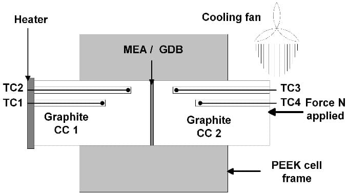
Figure 1: Schematic diagram of the through-plane thermal impedance and permeability measurements in the test cell. TC = K type thermocouple, CC = current collector, GDB = gas diffusion backing, MEA = membrane electrode assembly
Additional fuel cell measurement equipment
The current of the cell was controlled with an EL 300 or an EL 100 electronic load interfaced to an IM6 electrochemical workstation from Zahner-Elektrik GmbH & Co. EIS measurements were carried out in the range of 0.1 Hz to 5 kHz. High frequency (HF) resistance was calculated using impedance at 1 kHz.
The reactant humidification substation (Fuel Cell Technologies Inc.) was used. A calibration run indicated that the set point temperature was accurate at 40°C, but at 60 and 70°C, the real dew point was 2-3°C lower than the set point. The temperatures reported in this paper are the humidification system set points.
Pressure distribution measurements
The clamping pressure distribution on the GDBs was studied by replacing the MEA with a thin pressure-sensitive film and applying clamping pressure as usual. Color changes in the film revealed the pressure distribution. A Pressurex® Ultra Low film was used.
Gas diffusion backing samples
Since the focus of this study was on the development of the methods suitable for gas diffusion layer characterization, different commercial GDBs with highly varying properties were chosen for fuel cell measurements. Carbeltm CL is a material supplied by the manufacturer of the applied MEA (W. L. Gore & Associates, Inc.). SIGRACET® GDL 30-BB and GDL 10- BC (SGL Carbon AG) are dry-laid carbon papers. GDL 10-BC is developed especially for two-phase conditions. Double-Sided ELAT® (ELAT®-DS) by E-TEK, Inc. has very low porosity and permeability. The GDB samples were installed on the cathode side of the cell, and Carbeltm CL was used on the anode side, unless otherwise stated. Fresh GDBs were used in all measurements. ®SIGRACET® GDL 10-BA was used in the permeability measurements, since it is essentially a SIGRACET® GDL 10-BC without the 40µm microporous layer. Some of the material properties, as given by the manufacturers, are listed in Table 1.
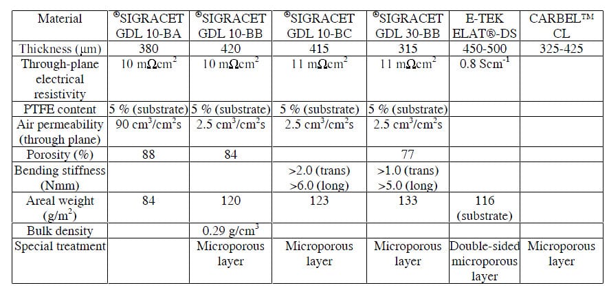
Table 1: GDB material properties given by manufacturers.
Membrane electrode assembly
PRIMEA® Series 5510 MEAs were used in all experiments. Platinum loading was 0.3 mg/cm2 on both anode and cathode. Etraglass 250 Pm PTFE-coated glass fiber thread was used as the gasket material (Oy ETRA AB). The gaskets were attached using two-sided adhesive (Scotch™ 467MP by 3M). A fresh MEA and fresh GDBs were used for each experiment.
As pre-treatment of the MEA, the cell was run at very low air surplus and cell voltage (under 0.1 V) for several hours at 60°C with high humidity (dew point 67-68°C) on the cathode side. The treatment was applied to both sides, i.e. the anode and cathode were interchanged at least once. According to our experience, a low cathode potential combined with high humidity is a good way to activate as-received electrodes both in singe cells and stacks.
Fuel cell testing practice
All fuel cell experiments were made at 60°C and the set point of the hydrogen humidifier was 63°C. When experiments with different current density levels were performed the air humidifier set points were 48°C and 60°C, respectively. The polarization curves were recorded with air and oxygen using the same flow rates. Curves were measured one after another in order to minimize the effect of changing electrode kinetics. The current density was held at each level for 15 minutes. When experiments with varying clamping pressure and constant current were made set points of 40 and 60°C were used on the cathode side. The former is in the single-phase region while in the latter case the end of the flow channel begins to flood at the applied gas volume flow rates. These humidity levels are referred to as low and high in the sections below.
In the fuel cell experiments, pure (>99.999%, AGA AB) oxygen, hydrogen and synthetic air were used. Excessive flows were used, 4.3 times stoichiometric for air and 5.5 for hydrogen. At the highest current (7A, 1 A cm-2) flow rates were 270 cm3 min-1 for H2 and 500 cm3 min-1 for air. In those measurements in which both air and oxygen were used, the flow rate of oxygen was the same as the one for air. All measurements were carried out at atmospheric pressure.
In the first part of the fuel cell measurements fuel cell performance was studied using polarization curves measured at different compression levels. The second part of the measurements was made using a constant current density (1 A cm-2) and varying dew point or clamping pressure. The experiments were performed mainly at high humidity since the focus of the study was flooding of the GDB. The high humidity dew point was chosen to be a couple of °C lower than the cell temperature since it has been shown that this is a critical range where drastic changes in performance are possible [1]. Measurements were usually performed twice with fresh samples.
Results and discussion
Characterization of physical properties
Porosity and pore size distribution
In Figure 2 the cumulative pore volume of three different materials is plotted against pore size. The measured porosities are significantly lower than those reported by the GDB suppliers in Table 1. Figure 3 shows the pore size distribution of the same materials.
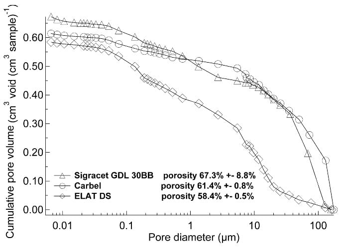
Figure 2: Cumulative pore volumes for uncompressed GDBs, measured by mercury intrusion porosimetry.
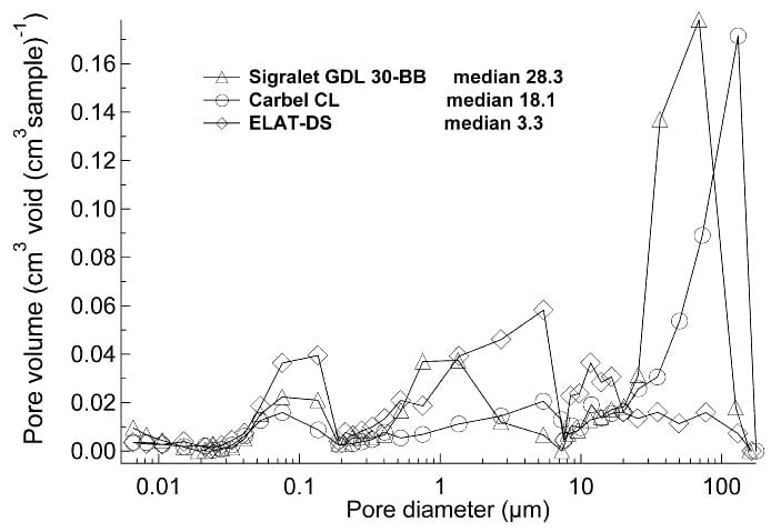
Figure 3: Pore size distributions from mercury porosimetry results, shown in Figure 2.
Mathias et al. have criticized the use of mercury porosimetry, since large pores are measured even though they do not pass all the way through the GDB [1]. They also give an introduction to different methods for measuring porosity and pore size distribution. All methods seem to have some limitations.
In all measurements the achieved porosity values include both the substrate and the microporous layer material. This is a serious limitation, since according to reports in the literature the microporous surface layer has an important role in water management [14, 30]. Therefore, porosity should be measured separately for the microporous layer and for the substrate material. Measurement of pore size under compression would be another interesting parameter. Here, also, the changes in the microporous layer and for the substrate material should be distinguished. Linking GDB porosity and pore size distribution to cell performance for two-phase conditions seems to be a very difficult task. Water transport in pores takes place mainly by capillary movement and for that purpose also surface properties inside the GDB should be measured.
Wetting properties
Average values from contact angle measurements are presented in Table 2. It can be seen that there a
re no significant differences between the samples. SIGRACET® GDL 10-BC and ELAT®-DS had the smoothest and the roughest surface, respectively. For SIGRACET® GDL 10-BC, an average standard deviation of 1.6 % was achieved with three measurements, but for ELAT®-DS, seven measurements yielded an average standard deviation of 4.3 %.

Table 2: Contact angle of GDB materials with water. Standard deviation of measurement results was used as error value.
The measured contact angle values ranged from 145 to 156 °. Surface wetting properties do not correlate directly with fuel cell performance, since the two best-performing materials included in this test, SIGRACET® 10-BC and Carbeltm CL, had the highest and lowest average contact angles, respectively. Moreover, the contact angle on the surface does not provide information about water behavior inside the material, which seems to be the performance-determining factor. New methods are needed for characterizing the GDB interaction with liquid water inside the GDB. Thermal impedance and electrical contact resistance Electrical bulk conductivity of the gas backing materials is usually in the range of 50-200 S/cm, but there can be large differences between in-plane and through-plane conductivity [1]. Bulk conductivity values in this range were achieved in our measurements and, in addition, it was found out that in-plane electrical conductivities were independent of the compression force. Therefore, the contribution of electrical bulk conductivity to the areal electrical resistance should be small (< 1mΩ cm2) and not dependent on the compression.
Thermal impedance and electrical contact resistance were measured for several GDB materials. The results of the experiments with SIGRACET® GDL 10-BC and Carbel CL are illustrated in Figure 4. As can be seen in Figure 4 both thermal impedance and contact resistance are strongly dependent on clamping pressure. The measured thermal impedances for these and other GDBs were usually in the order of 7-15 K cm2 W-1, including two GDBCC contacts and bulk material, when the clamping pressures were 3 to 10 bar.
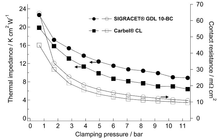
Figure 4: Thermal impedance and contact resistance as functions of clamping pressure for SIGRACET® GDL 10-BC and CARBEL™ CL. The values for thermal impedance and contact resistance include two interfaces and bulk materials.
If these values were to be used to calculate thermal conductivity for the bulk material, the corresponding value would be 0.2-0.4 W m-1K-1, which is in the same order of magnitude as measured by Vie [31]. However, such low bulk values for thermal conductivity are unrealistic, since GDBs are graphitized carbon fiber materials with an electrical conductivity of 5-10% of that of graphite. Since thermal and electrical bulk values for porous materials usually are interrelated it is reasonable to assume that the thermal conductivity of a GDB is also 5-10% of that of graphite, i.e. 5-10 W m-1K-1. This means that the interfaces are clearly the dominating source of the thermal impedance with a value of around 3-7Kcm2W-1. With a rib/channel ratio of 1:1 the corresponding temperature drop between bipolar plate and GDB for an operating fuel cell would be 6-14 °C at a heat flux of 1 W per cm2 GDB area (2 W per cm2 rib area).
The measured electrical contact resistances are in the same range as reported in the literature [1]. Reasonable contact resistances (less than 10 m: per contact) are reached at pressures under 10 bar. Microporous layers were found to increase contact resistance as also shown by Murata et al. [15].
The results of this section show clearly that the main sources for thermal impedance and areal electrical resistance are the interfaces, not the bulk materials. These properties depend on the clamping pressure in a similar way and pressures of around ten bar are required to reach sufficiently low values. However, the findings of this section are limited to the GDB-CC interface. What remains as a topic for further research is the contact resistance and thermal impedance of the GDB-MEA interface.
Gas permeability
In-plane and through-plane gas permeability were measured for GDBs. Gas permeability can be calculated using Darcy’s equation only if material thickness is known [1, 24]. The change in thickness was also measured but due to the low measurement accuracy the permeability values here are calculated using the thickness of uncompressed GDB. If decrease in thickness is taken into account the minimum values at the highest pressure are approximately 30-50% larger, the difference being largest for soft carbon cloths.
As can be seen from the data in Figure 5, ELAT®-DS has an order of magnitude lower inplane permeability than other GDBs. Figure 5 also shows how the permeability of Carbel CL decreases much more than that of SIGRACET® GDL 10-BC when the clamping pressure is increased. This is because carbon cloths are usually mechanically much less rigid [1]. Permeability was measured for several other commercial GDBs and all were in the range of 10-12 – 10-11 m2.
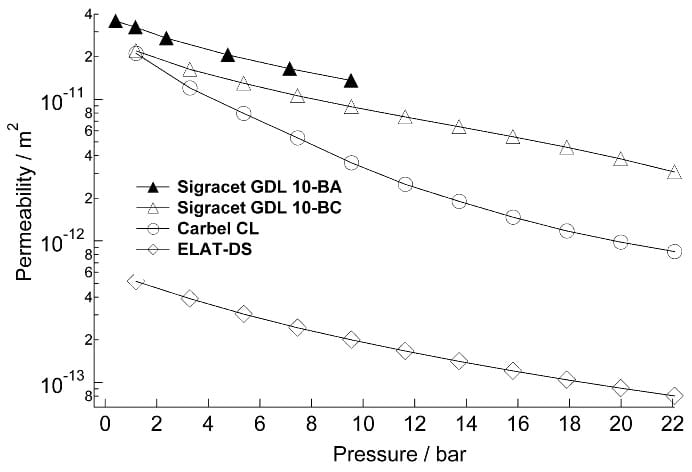
Figure 5: In-plane gas permeability results for SIGRACET® GDL 10-BA, SIGRACET® GDL 10-BC, CARBEL™ CL and ELAT®-DS as a function of clamping pressure.
GDBs are also very different when in-plane and through-plane ratios are compared. Mathias et al. have measured this ratio to be about 1 for Toray TGP–H–060 carbon-fiber paper [1]. However, this is not always true, especially when a thin and dense microporous surface layer is applied onto the substrate. As seen from Table 3 there are differences of two orders of magnitude in in-plane/through-plane ratio between different GDBs. For modeling it is important to take into account that some GDBs have very clear double-layer structure, while others are more homogeneous. The microporous layer usually has much smaller permeability than the substrate material. For example, comparing the results of SIGRACET® GDL 10-BC and SIGRACET® GDL 10-BA in Table 3 it can be estimated that the 40 micrometer thick microporous layer on SIGRACET® GDL 10-BC has a through-plane permeability of less than 3-14 m2, that is three orders of magnitude lower than for the substrate material.

Table 3: In-plane and through-plane gas permeability of different GDB materials.
Mechanical properties
Mechanical properties (compressive and flexural behavior) of the GDB are also very important. These properties determine the surface pressure distribution and the thickness and porosity of the GDB in the cell. Figure 6 illustrates the surface pressure distributions obtained with Pressurex® pressure-sensitive film. The cell was assembled placing a Pressurex® film instead of a MEA and applying clamping pressure as usual. The pressure distributions A and C were obtained using Carbel CL ; B and D were obtained using SIGRACET® GDL 10-BC. In A and B the flow field was a single spiral channel. In C and D a net-type flow field was used, more details of the net structure can be found in a paper by Noponen et al. [32].
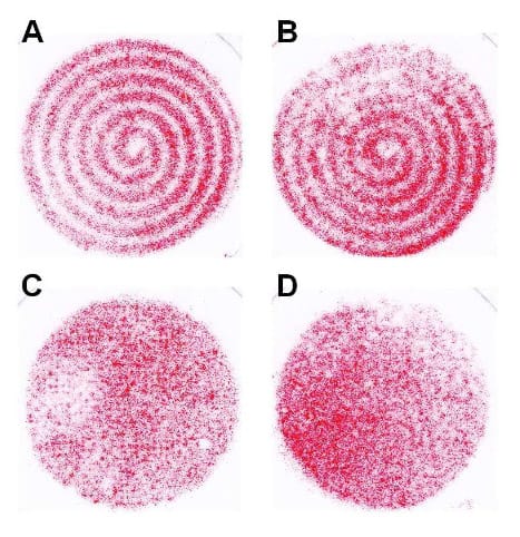
Figure 6: Pressure test with pressure-sensitive foil illustrating differences in pressure distribution when different GDBs (A and C: Carbel CL, B and D: SIGRACET® GDL 10- BC) and flow fields are used. Compression force 12 bar for A and B and 14 bar for C and D, calculated on plane area. Darker color indicates higher pressure.
As can be seen from Figure 6, mechanically more rigid carbon paper distributes the pressure more evenly than softer carbon cloth. When a net is used, the form of the net is visible in the clamping pressure distribution C while it is absent in D. Figure 6A shows that when soft carbon cloth is used the pressure above the channels is only 10-20% of the pressure above the ribs. This leads to highly uneven permeability, porosity, thermal impedance and contact resistance throughout the material. When pressure distribution data is used together with compressibility, permeability and thermal impedance data for the GDB, a more complete set of parameters can be obtained for model development.
Even if less compressible carbon papers can distribute pressure better locally, they have also serious drawbacks. If there are deviations in the thickness of some of the repeating components in the stack this leads to very uneven pressure distribution in the cell. Therefore, rigid gas diffusion materials require much better tolerances or increased flexibility from other components than softer carbon cloths.
Fuel cell measurements
GDB characterization by polarization curve measurements
Several series of polarization curve measurements were performed on Carbel CL using variable compression levels. The results of two polarization experiments are illustrated in Figure 7. The best performance (highest cell voltage) at high current densities is reached at compression levels 9.7 bar and the optimum compression level is therefore between 4.3 and 18.6 bar. These graphs are iR-corrected since the increase in mass transfer overpotential due to loss of porosity at high clamping pressures can more easily be detected when the effect of changing resistance is eliminated. The optimum compression level for not iR-corrected results is also between 4.3 and 18.6 bar. The increase in mass transfer overpotential can be distinguished clearly when the difference in cell voltage between polarization curves measured with oxygen and air are plotted. As Figure 7 a-b show, this voltage difference increases significantly when compression is increased from 9.7 to 18.6 bar. This increase is almost similar at low and high humidity levels indicating that the mass transfer is mainly due to decreased porosity, not flooding of the GDB.
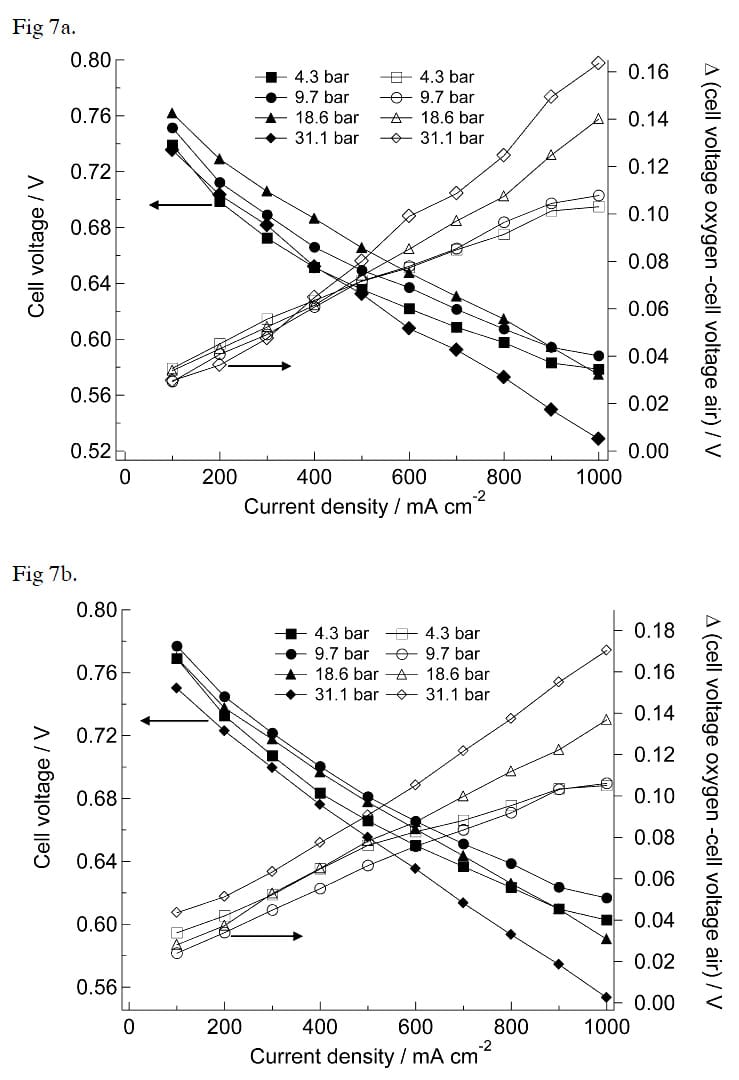
Figure 7: IR-corrected polarization curves with air and cell voltage difference between measurements with air and oxygen. GDB: CARBEL™ CL. a) Cathode humifier set-point 48°C b) Cathode humifier set-point 60°C.
The measured HF cell resistances are given in Table 4. The resistances of the graphite current collectors, contributing 20 mΩ cm2 in areal resistance, are included in the values. When these results are compared to those in Figure 4 it can be seen that the relative decrease in areal resistance is much larger than in ex-situ measurements when clamping pressure is increased. In the ex-situ measurements only contact resistances between graphite and GDB were measured. In the cell there are also two GDB-MEA contacts and it seems that these contacts have about twice as high as resistance as the GDB-CC contacts.

Table 4: High-frequency areal resistances at different clamping pressure levels. Data is from the same measurement as in Figure 7.
The results of this section show that the polarization measurements with changing humidity and compression levels can be a valuable method to characterize the performance of GDBs. However, several drawbacks of using polarization curve measurements were also found:
1. Since there is larger heat production on the electrode at high current densities there are also steeper temperature profiles. If air surplus is kept constant flooding may occur at low current densities while being absent at higher current densities.
2. The measurements are time-consuming and therefore only a limited number of compression levels can be studied in a reasonable time. This is true especially if impedance curves are measured, since the required equilibrium conditions are reached only after 10-20 minutes.
3. Changes in humidity change the kinetics of the electrode reactions even if electrode preactivation is applied before experiments.
4. The temperature of the exhaust gas is difficult to measure at low current densities and gas flows, since the surrounding solid material has a large effect on the temperature probes.
Figure 7 a-b also shows that the effect of mass transfer is clearly visible only at high (>0.5 A cm-2) current densities. Therefore, the measurements at low current densities are not needed when mass transfer is studied.
GDB characterization using variable clamping pressure
CarbelTM CL
The results with CarbelTM CL at high humidity in Figure 8a show that there is an increase in cell voltage until a compression of 20 bar is reached. The iR-corrected cell voltage has its maximum already at 10 bar. In other measurements the optimum performance was reach when the compression was between 20 and 25 bar. A significant decrease in cell voltage could be detected only when the clamping pressure was close to 30 bar. These results are in accordance with the polarization curve measurements shown in the previous section. During the measurement impedance spectra were also recorded. The results in Figure 8b show a) that the HF resistance is a major source of losses at low compression forces and b) how mass transfer losses rise with increasing compression force.
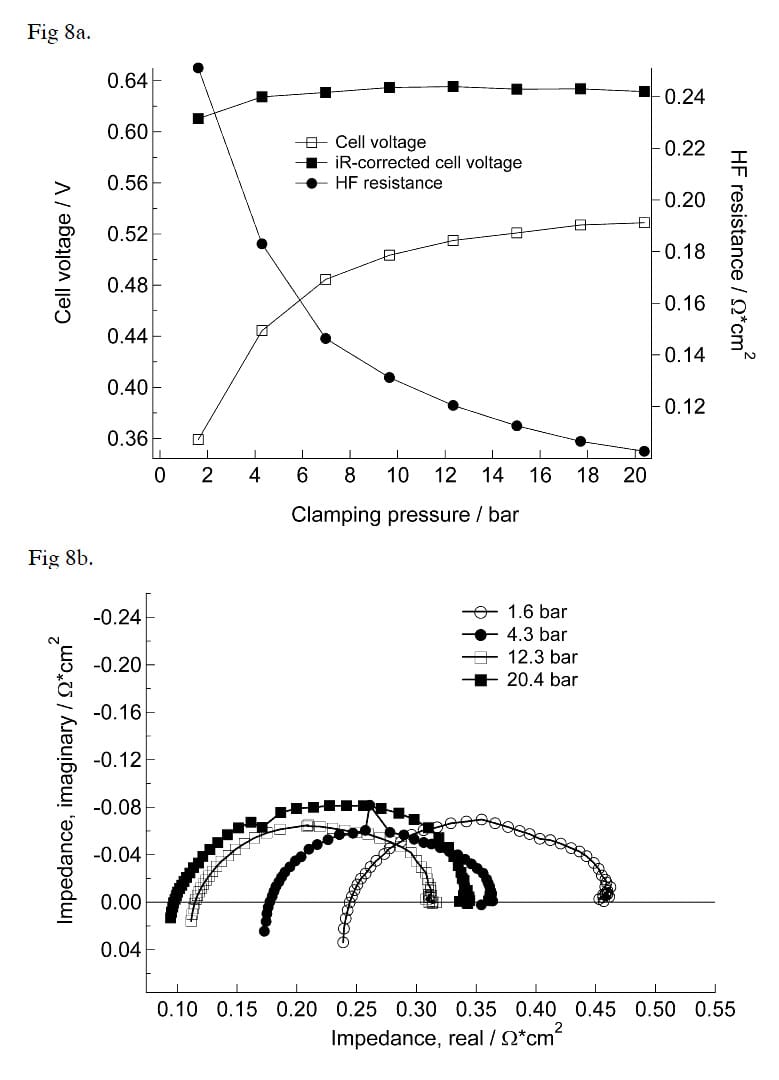
Figure 8: a) Cell voltage and high-frequency resistance at 1 A cm-2 for CARBEL™ CL at high humidity. b) Nyqvist plots at different clamping pressures.
Results with CarbelTM CL at low humidity, in Figure 9 a-b, show that the optimum clamping pressure at low humidity is significantly higher than for high humidity. There may be several reasons for this difference in behavior. As clamping pressure is increased the thermal impedance decreases leading to a smaller temperature difference between the CC and the MEA. As the temperature of membrane decreases the membrane conductivity increases, since absolute humidity is constant. This effect is larger at low humidities than at high humidities. In addition, at low humidity there is no increased flooding of the GDB due to decreased temperature difference, while at high humidity some flooding of the GDB may occur. Comparison of the Nyqvist plots in Figures 8 b and 9 b shows that the mass transfer properties are changing in an almost similar way at low and high humidities. This leads to the conclusion that the increase in mass transfer resistance is mainly due to loss of porosity, not due to flooding. This result is essentially the same as achieved by polarization measurements in the previous
section.
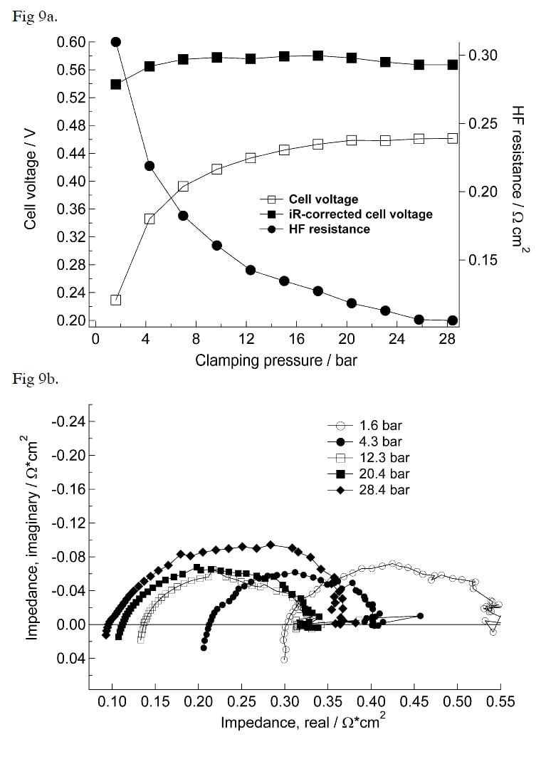
Figure 9: a) Cell voltage and high-frequency resistance at 1 A cm-2 for CARBEL™ CL at low humidity. b) Nyqvist plots at different clamping pressures.
SIGRACET® carbon papers
Figure 10a shows the results with SIGRACET® GDL 30-BB and SIGRACET® GDL 10-BC measured at high humidity. These results show that the optimum compression for SIGRACET® GDL 30-BB is fairly low, about 10 bar. The decrease in iR-corrected cell voltage for SIGRACET® GDL 30-BB is 80-90 mV as pressure is increased. On the contrary, the optimum compression is not reached with SIGRACET® GDL 10-BC. Impedance data for SIGRACET® GDB 30-BB, presented in Figure 10a, also indicates a very large increase in mass transfer resistance. For SIGRACET® GDL 10-BC impedance data was similar to that of Carbel CL. The results with SIGRACET® GDL papers measured at low humidity are quite similar to those measured with Carbel CL, the difference being lower increase in the mass transfer semicircle in the Nyqvist plots. The performance was increased up to maximum pressure.
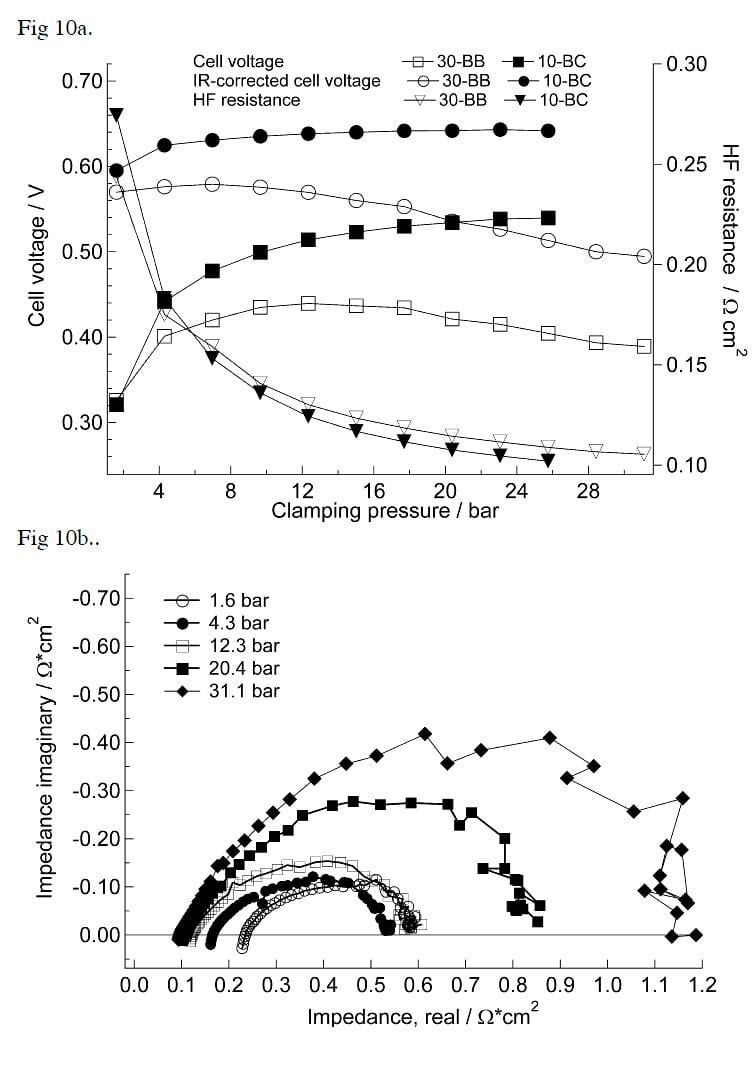
Figure 10: a) Cell voltage and high-frequency resistance at 1 A cm-2 for SIGRACET® GDL 30-BB and SIGRACET® GDL 10-BC at high humidity. b) Nyqvist plots at different clamping pressures from measurements with SIGRACET® GDL 30-BB.
ELAT®-DS
The results with ELAT®-DS at low and high humidities are shown in Figure 11a. The results under two-phase conditions show that ELAT®-DS floods when the compression force is increased. The results under single-phase conditions, on the other hand, show that the optimum compression is already reached at about 12-15 bar; the drop in iR-corrected voltage between the maximum voltage and the voltage at 30 bar was 55 mV, while for Carbel CL and SIGRACET® GDL papers the drop was only about 15-20 mV. This, and the Nyqvist plot, shown in Figure 11b, show large increase in mass transfer resistance.
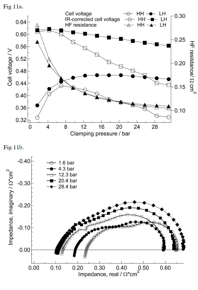
Figure 11: a) Cell voltage and high-frequency resistance at 1 A cm-2 for ELAT-DS at low humdity (LH) and high humdity (HH). b) Nyqvist plots at different clamping pressures from measurements with low humidity.
The results, measured under single-phase conditions, indicate that the permeability of ELAT®-DS (10-13 m2) is too low while the other GDBs have a permeability (10-12 m2) that seems to be sufficient. However, it should be noted that these experiments were performed under conditions that correspond to the inlet of the fuel cell. The average mole fraction of oxygen (poxygen/ptotal) in the gas channels was about 0.18 due to high air surplus and low vapor pressure. Under more realistic fuel cell conditions the average mole fraction of oxygen is 30- 40% lower and at the end of the cell the mole fraction of oxygen can be as low as 0.05. Therefore, the diffusion overpotential can become significant at single-phase conditions even if GDBs with a permeability of 10-12 m2 are used.
GDB characterization using variable cathode dew points
Carbel CL
The results in previous sections show clearly that the effect of compression is strongly connected to flooding of the GDB in the two-phase region. To further study the flooding of GDBs, a series of experiments with varying cathode humidity was conducted. In these measurements the compression force as well as the current (1 A cm-2) were kept constant. GDB characterization by changing cathode humidity has earlier been applied by Mathias et al., but they used constant voltage instead of constant current, which did not allow accurate control of gas excesses [1]. In addition, large changes in current density lead to changes in temperature profile as heat production is changed.
The results with Carbel CL are given in Figure 12a-b. These results again show that Carbel CL works excellently at two-phase conditions. When two-phase conditions are reached there is only a small (< 20mV) drop in cell voltage. This is due to a slight increase in mass transfer resistance that also can be seen from the impedance data in Figure 12b.
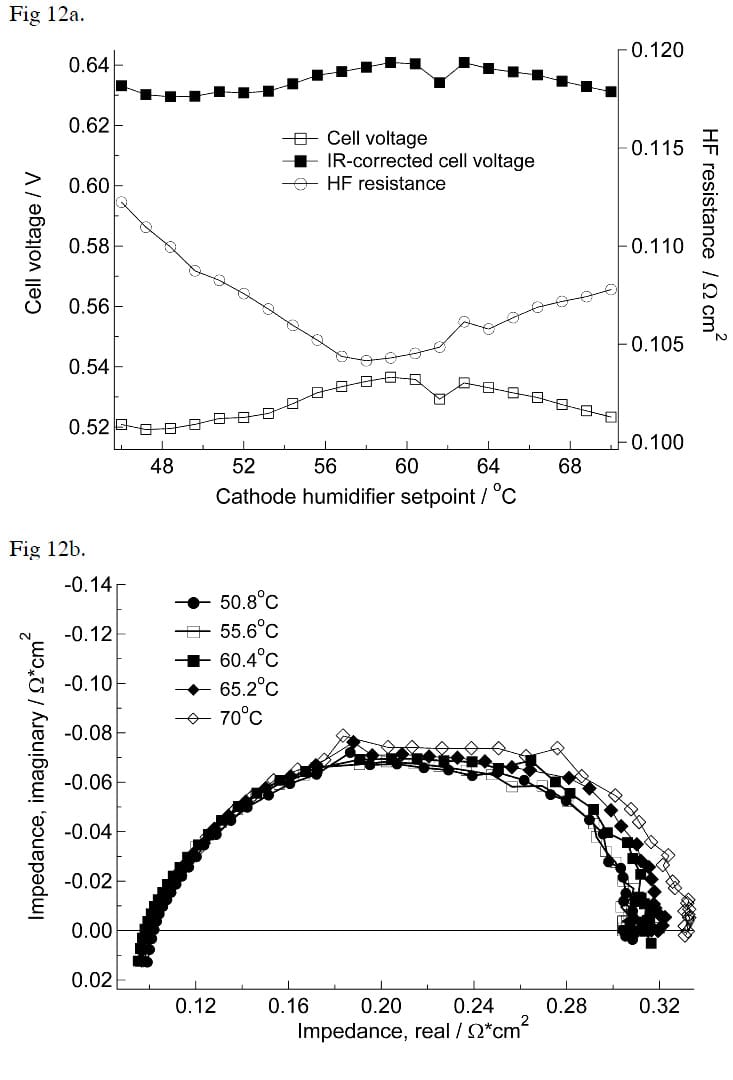
Figure 12: a) Cell voltage and high-frequency resistance at 1 A cm-2 for CARBEL™ CL as a function of cathode humidifier setpoint. Compression force 17.7 bar calculated on the ribs. b) Nyqvist plots at different humidities.
SIGRACET® carbon papers
Results with two different SIGRACET® carbon papers (GDB 30-BB and 10-BC) are given in Figure 13a and 13b. For SIGRACET® GDL 10-BC the humidity sweep was also performed with oxygen. These results show that SIGRACET® GDL 30-BB works excellently at dry and at mildly flooding conditions. However, when the humidifier setpoint exceeds 50°C the cell voltage drops drastically, about 200 mV, due to a very high level of flooding. On the contrary, when the same experiment is carried out with SIGRACET® GDL 10-BC, which is optimized for two-phase conditions, the corresponding drop in cell voltage is only 25 mV.
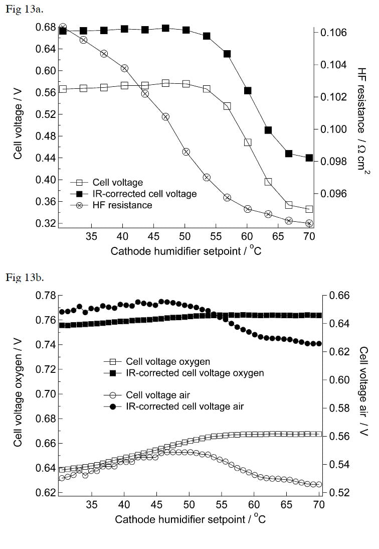
Figure 13: a) Cell voltage and high-frequency resistance at 1 A cm-2 for SIGRACET® GDL 30-BB as a function of cathode humidifier setpoint. Compression force 31.1 bar calculated on the ribs. b) Cell voltage with air and oxygen at 1 A cm-2 for SIGRACET® GDL 10-BC as a function of cathode humidifier setpoint. Compression force 28.4 bar calculated on the ribs.
In Figure 13b, the results recorded using air and oxygen with SIGRACET® GDL 10-BC are compared. The results with pure oxygen show that there is no decrease in performance when humidity is increased in the critical range (50°C to 60°C). On the contrary, the performance improves due to better humidification. This result suggests that the electrode is not flooded, when this particular combination of GDB and MEA was used. If the electrode were flooded by a continuous water film between the GDB and the electrode, the performance should decrease also with pure oxygen.
The results with SIGRACET® carbon papers show that small differences in the properties of the GDB lead to drastic changes in the cell performance in two-phase region. The used SIGRACET® GDBs have similar microporous layers but different substrate materials. In this particular case the properties of the substrate seem to determine the flooding behavior. A hydrophobic surface layer with the right properties is also required for water management, but it also creates an additional diffusion barrier and increases contact resistance. An optimal microporous layer should have high through-plane permeability while maintaining sufficient water management properties.
Water management on the anode side is much less critical than on the cathode side. GDBs that do not work at all on the cathode side in the two-phase region can work excellently on the anode side. In fact, the best cell performance (570 mV at 1 A cm-2) at two-phase conditions was obtained when SIGRACET® GDL 30-BB was installed on the anode side and Carbel CL on the cathode side. The GDBs on the anode side ca
n probably be much less porous and do not require the same hydrophobic properties as on the cathode side. Therefore, on the anode side, GDBs that have lower thermal impedances and contact resistance should be used.
ELAT-DS
The humidity sweep for ELAT®-DS was qualitatively similar to that of SIGRACET® GDL 30-BB. The decrease in cell potential due to flooding of the GDB was about 100 mV. The results showed again that ELAT®-DS works much more poorly than SIGRACET® GDL 30- BB and Carbel CL at low humidity, due to low permeability.
Measurement of exhaust gas temperature in operating fuel cell
The temperature difference between exhaust gases and current collectors (CC) was measured to study whether the thermal impedance can be measured in the operating fuel cell. It was found that this is not an easy task. Installation of the temperature probes should be done in such a way that the thermocouple is laid freely in the air stream without contact with any solid material close to the junction. Any such contact will induce an error due to heat conduction between solid material and the junction [33]. Successful installation and measurements were achieved only infrequently.
The result of one successful measurement is shown in Figure 14, which shows the same kind of correlation between contact resistance and thermal impedance as can be seen in ex-situ measurements in Figure 4. The gas flowing in the rectangular gas channels is in contact with three cold walls (current collector) and with one hot wall (GDB). Depending on the heat transfer rates, the temperature difference between GDB and CC should be 2-3 times larger than the temperature difference between exhaust gas and CC. Therefore, when the gas is at 1.5 to 3°C higher temperature than the current collector, the GDB should have at least 3 to 6°C higher temperature than the CC. Estimated thermal impedance for GDB-CC contact from these results is in the order of 3 to 6 K cm2W-1, which is in good agreement with the ex-situ results.
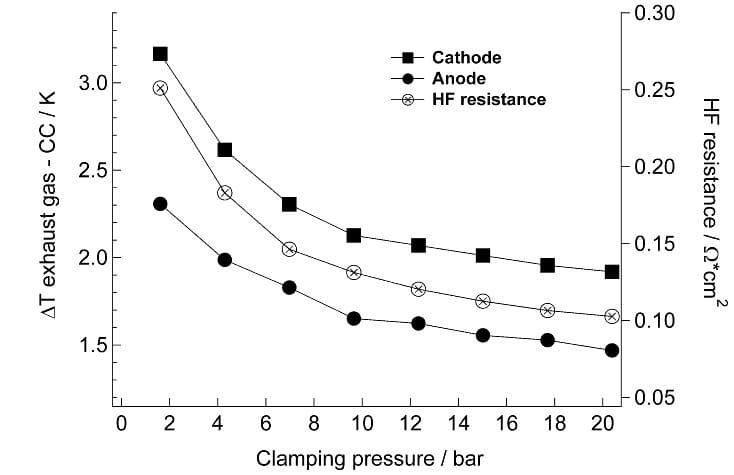
Figure 14: Temperature difference between exhaust gas and current collectors (CC), and highfrequency (HF) resistance as functions of clamping pressure. Data is from the same measurement as in Figure 8.
The measurement of temperatures inside the fuel cell is a very complicated issue. In addition to complicated instrumentation, care should be taken that the current density along the channel be even. This can only be achieved at high reactant surplus, at high humidity and using GDBs with good water management properties. For example, if the GDB is flooded, the current density decreases at the end of the channel and the temperature difference decreases, too. Figure 15 shows the results of an experiment in which this phenomenon was observed.
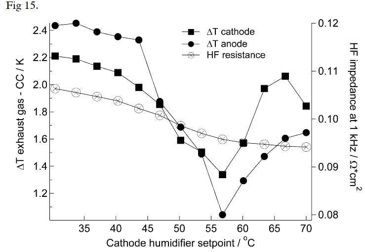
Figure 15: Temperature difference between exhaust gases and current collectors (CC), and high-frequency resistance as functions of cathode humidity. Data is from the same measurement as in Figure 13a.
As the results in Figure 15 show, the temperature differences decrease drastically between 45 and 57 °C, since at the end of the channel the GDB gets flooded and local current density decreases. Above 57 °C the temperature difference increases again, since the current density evens out as the flooding reaches the whole area of the GDB.
Quantitative measurements of the temperature gradients inside the fuel cell require better thermocouples and instrumentation than applied in the measurements in this paper. Temperature gradients inside the fuel cell have previously been measured by Vie [31], but without variation of clamping pressure. In his thesis, Vie also gives detailed instructions for manufacturing miniature thermocouples for laboratory purposes. However, our experience is that ex-situ measurements can provide more accurate thermal impedance values with less complex experimental arrangements than fuel cell experiments.
These fuel cell results demonstrate that the effect of GDB type on cell performance can be determined, if the clamping pressure and humidity can be controlled in a fuel cell. The effects of flooding of GDB and loss of permeability are easily studied. The loss of permeability can also be studied ex situ in a reliable way. On the contrary, the water management properties, namely capillary forces inside the GDB, are very difficult to study ex situ. Porosity and pore size distribution can be studied ex situ but the determination of wetting properties (surface angle) inside the GDB seems to be a challenging task.
Conclusions
In this study different gas diffusion backings were examined both ex situ and in situ. The most efficient method for characterizing GDBs was found to be galvanostatic fuel cell experiments with varying cathode reactant humidity. The effect of compression on cell performance was found to be largest when the GDBs have poor water management properties or low permeability.
Thermal impedance and contact resistances were found to correlate and interfaces were found to be the main source of thermal impedance. The thermal impedances were found to be large enough to create significant temperature profiles inside the fuel cell. Thermal impedance had a clear effect on GDB flooding whenever water management properties of the GDB were insufficient. Increasing compression force reduces both thermal impedance and contact resistances. If the cell is operated under single-phase conditions or the water management properties and permeability are adequate, the optimal compression pressure is above 30 bar.
Permeability measurements and fuel cell experiments under single-phase conditions indicate that a permeability of 10-12 m2 should be sufficient for GDBs. It was found that it is much more important to avoid flooding and loss of porosity under two-phase conditions than to maximize permeability under single-phase conditions.
The measurement of porosity and pore size distribution was found to be a very difficult task. These parameters should be measured separately for substrate material and microporous layer. No correlation was found between surface wetting properties and fuel cell performance under two-phase conditions.
Acknowledgements
The financial support of the National Technology Agency of Finland and the Swedish Foundation for Strategic Environmental Research (MISTRA) is gratefully acknowledged. The authors would like to thank SGL Carbon for providing gas diffusion backing material samples.
References
- M. Mathias, J. Roth, J. Fleming and W. Lehnert, in Handbook of Fuel Cells – Fundamentals, Technology and Applications, Vol. 3: Fuel Cell Technology and Applications, Chapter 46, W. Vielstich, H. Hasteiger and A. Lamm, Editors, John Wiley & Sons, Ltd. (2003).
- V. Mehta and J.S. Cooper, J. Power Sources, 114, 32 (2003).
- D. Oei, J.A. Adams, A.A. Kinnelly, G.H. Purnell, R.I. Sims, M.S. Sulek, D.A. Wernette, B. James, F. Lomax, G. Baum, S. Thomas and I. Kuhn, in Direct hydrogen fueled proton exchange membrane fuel cell system for transportation applications, Final Technical Report, Report no. DOE/CE/50389-505, Ford Motor Company, (2000).
- L.R. Jordan, A.K. Shukla, T. Behrsing, N.R. Avery, B.C. Muddle and M. Forsyth, J. Appl. Electrochem. 30, 641 (2000).
- C. S. Kong, D-Y. Kim, H-K. Lee, Y-G. Shul and T-H. Lee, J. Power Sources 108, 185 (2002).
- E. Antolini, E. E. Passos and E. A. Ticianelli, J. Power Sources 109, 477 (2002).
- E. Antolini, E. E. Passos and E. A. Ticianelli, J. Appl. Electrochem. 32, 383 (2002).
- J. Moreira, A. L. Ocampo, P. J. Sebastian, M. A. Smit, M. D. Salazar, P. del Angel, J. A. Montoya, R. Pérez and L. Martínez, Int. J. Hydrogen Energy 28, 625 (2003).
- J. Soler, E. Hontano and L. Daza, J. Power Sources 118, 172 (2003).
- Y-G. Yoon, G. -G. Park, T-H. Yang, J-N. Han, W-Y. Lee and C-S. Kim, Int. J. Hydrogen Energy, 28, 657 (2003).
- T. Springer, M. Wilson and S. Gottesfeld, J. Electrochem. Soc. 140, 3513 (1993).
- T. Springer, T. Zawodzinski, M. Wilson and S. Gottesfeld, J. Electrochem. Soc. 143, 587 (1996).
- B. Mueller, T. Zawodzinski, J. Bauman, F. Uribe, S. Gottesfeld, E. De Castro and M. De Marinis, in Proton Conducting Membrane Fuel Cells II, S. Gottesfeld, T. F. Fuller and G. Halpert Editors, PV 98-27, p.1, The Electrochemical Society Proceedings Series, Boston, Massachusetts (1999).
- Z. Qi and A. Kaufman, J. Power Sources 109, 38 (2002).
- M. Murata, D. L. Wood III, M. Maendle and P. M. Wilde, 2002 Fuel Cell Seminar: Abstracts, p.41, Palm Springs, California, November 18-21, (2002).
- R. Allen, R. Linstrom and W. Juda U.S. Pat. 4,293,396 (1981).
- M. De Marinis, E. De Castro, R. Allen and K. Shaikh, European Patent Application EP 0,928,036 (1999).
- H. Kato, U.S. Pat. 6,127,059 (2000).
- V. Rosenmayer, International Patent Application WO 00/14816 (2000).
- M. Wilson, International Patent Application WO 00/25377 (2000).
- N. Djilali and D. Lu, Int. J. Therm. Sci. 41, 29 (2002).
- W. Lee, C-H. Ho, J.V. Van Zee and M. Murthy, J. Power Sources 84, 45 (1999).
- D. Natarajan and T. V. Nguyen, J. Electrochem. Soc. 148, 1324 (2001).
- M. Mikkola, Master’s Thesis, Helsinki University of Technology, Finland (2001). Available on the WWW at URL: https://www.hut.fi/Units/AES/studies/dis/mikkola_abs.htm
- P. Gode, J. Ihonen, A. Strandroth, H. Ericson, G. Lindbergh, M. Paronen, F. Sundholm, G. Sundholm and N. Walsby, Fuel Cells, 3, 21 (2003).
- J. Ihonen, F. Jaouen, G. Lindbergh and G. Sundholm, Electrochim. Acta, 46, 2899 (2001).
- M. Arif, D. Jacobson and R. Satija in Hydrogen, Fuel Cells and Infrastructure Technologies Program, 2002 Annual Progress Report, U.S. Department of Energy, Report no. DOE/EERE/HFIT-2002/001, p. 438 (2002).
- A.B. Geiger, A. Tsukada, E. Lehmann, P. Vontobel, A. Wokaun and G.G. Scherer, Fuel Cells 2, 92 (2002).
- F. Barbir, J. Braun and J. Neutzler, New Mat. Electrochem. Syst. 2, 197 (1999).
- G. Scherer, Solid State Ionics 94, 249 (1997).
- P. Vie, Doctoral dissertation, Norwegian University of Science and Technology, Trondheim, Norway (2002)
- M. Noponen, J. Ihonen, A. Lundblad and G. Lindbergh, J. Appl. Electrochem. in press
- R. B. Bird, W. E. Stewart and E. N. Lightfoot, Transport Phenomena, 2nd ed., p. 309, Wiley & Sons (2002).


