F. Curà1,a, G. Curti1, A. Mura1, V.Cuffaro1
1Politecnico di Torino, Dipartimento di Meccanica, Torino, Italy
1 Introduction
Spline couplings are mechanical devices commonly used to join two shafts. Accordingly to the type of spline (straight teeth, crowned teeth, etc ) and gap between the teeth, joined shafts may have certain positioning errors, as misalignments or inclinations. Spline couplings utilised on aerospace applications need more accurate dimensioning in order to reduce the weight and to control failure mechanisms (as an example like fretting fatigue), then an accurate study about loads distribution on the tooth surface is needed, in particular pressure distribution.
Many theoretical studies about pressure distribution are available in literature [1], [2], on the other hand, experimental analysis are very rare. The aim of this work is to verify by means of an experimental set-up the theoretical results available in literature [1], [2], [5] about pressure distribution on spline couplings.
2 Pressure distribution
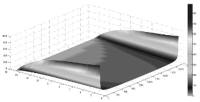
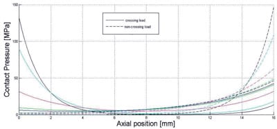
The pressure distribution on a spline tooth is far from uniform [3], [4] and it varies along both length and height of the teeth as shown in Figure 1. By considering an ideal spline (without manufacturing errors), the pressure distribution depends on the stiffness of both toots and shaft, and also depends on the load behavior (crossing and non crossing load) [5]; as shown in Figure (2).

Fig. 1. Pressure distribution along the spline sleeve tooth profile.
An experimental investigation has been developed in order to verify how well theoretical models can reproduce the real pressure distribution, in some load cases. A dedicated testbed, that is capable of generating a constant torque on the spline coupling, has been set-up to make the experimental tests.
To overcome the difficulties in measure the pressure distribution by means of normal pressure sensors, a special film called PressureX® has been interposed on the surface of the teeth.
This film can change its colour depending on the corresponding value of the pressure distribution in a well defined area.
A dedicated software developing an image correlation analysis has been employed to relate both colours and pressure values.

Fig. 2. Pressure distribution with crossing and non-crossing load.
References
- A. Barrot, M. Paredes, M. Sartor, Determining both radial pressure distribution and torsional stiffness of involute spline couplings Proc. IMechE Vol. 220 Part C: J. Mechanical Engineering Science (2006)
- Tatur, G. K. and Vygonnyi, A. G. Stress sources and critical stress combinations for splined shaft ASME, J. Mech. Des., 1969, XLIX(4), 23–29
- Adrien Barrot, Manuel Paredes, Marc Sartor Extended equations of load distribution in the axial direction in a spline coupling Engineering Failure Analysis 16 (2009) 200–211
- Tjernberg Load distribution in the axial direction in a spline coupling Engineering Failure Analysis Volume 8 (2001)
- V. Cuffaro Calcolo analitico delle sollecitazioni e deformazioni in un accoppiamento scanalato Master Thesis Politecnico di Torino 2009(in Italian).


