Abd Rahim Abu-Bakar
Department of Automotive Engineering, Faculty of Mechanical Engineering
Universiti Teknologi Malaysia, 81310 UTM Skudai, Johor, Malaysia
Huajiang Ouyang
Department of Engineering, University of Liverpool
Brownlow Street, Liverpool L69 3GH, U.K.
Abstract
Friction-induced vibration and noise emanating from car disc brakes is a source of considerable discomfort and leads to customer dissatisfaction. The high frequency noise above 1 kHz, known as squeal, is very annoying and very difficult to eliminate. There are typically two methods available to study car disc brake squeal, namely complex eigenvalue analysis and dynamic transient analysis. Although complex eigenvalue analysis is the standard methodology used in the brake research community, transient analysis is gradually gaining popularity. In contrast with complex eigenvalues analysis for assessing only the stability of a system, transient analysis is capable of determining the vibration level and in theory may cover the influence of the temperature distribution due to heat transfer between brake components and into the environment, and other time-variant physical processes, and nonlinearities. Wear is another distinct aspect of a brake system that influences squeal generation and itself is affected by the surface roughness of the components in sliding contact. This chapter reports recent research into car disc brake squeal conducted at the University of Liverpool. The detailed and refined finite element model of a real disc brake considers the surface roughness of brake pads and allows the investigation into the contact pressure distribution affected by the surface roughness and wear. It also includes transient analysis of heat transfer and its influence on the contact pressure distribution. Finally transient analysis of the vibration of the brake with the thermal effect is presented. These studies represent recent advances in the numerical studies of car brake squeal.
Abstract
Passenger cars are one main means of transportations for people travelling from one place to another. Indeed, vehicle quietness and passenger comfort issues are a major concern. One of the vehicle components that occasionally generate unwanted vibration and unpleasant noise is the brake system. As a result, carmakers, brake and friction material suppliers face challenging tasks to reduce high warranty payouts. Akay (2002) estimated that the warranty claims due to the noise, vibration and harshness (NVH) issues including brake squeal in North America alone were up to one billion US dollars a year. Similarly, Abendroth and Wernitz (2000) noted that many friction material suppliers had to spend up to 50 percent of their engineering budgets on NVH issues.
In a recent review, Kinkaid et al (2003) listed a wide array of brake noise and vibration phenomena. Squeal, creep-groan, moan, chatter, judder, hum, and squeak are among the names that can be found in the open literature. Of these noises, squeal is the most troublesome and irritant one to both car passengers and the environment, and is expensive to the brakes and car manufacturers in terms of warranty costs (Crolla and Lang, 1991). It is well accepted that brakes squeal is due to friction-induced vibration or self-excited vibration via a rotating disc (Chen et al, 2003a). Brake squeal frequently occurs at frequency above 1 kHz (Lang and Smales, 1983) and is described as sound pressure level above 78 dB (Eriksson, 2000) or usually at least 20dB above ambient noise level in the automotive industry.
Brake squeal has been studied since 1930’s by many researchers through experimental, analytical and numerical methods in an attempt to understand, predict and prevent squeal occurrence. Although experiments used to be the more credible way of studying disc brake squeal (Nishiwaki et al, 1990; Yang and Gibson, 1997), there has been a great advancement in the numerical analysis methodology in recent years. More specifically, the finite element (FE) method is the preferred method in studying brake squeal. The popularity of finite element analysis (FEA) is due to the inadequacy of experimental methods in predicting squeal at early stage in the design process. Moreover, FEA can potentially simulate any changes made on the disc brake components much faster and easier than experimental methods. A recent review (Ouyang et al, 2005) stated that experimental methods are expensive due to hardware costs and long turnaround time for design iterations. In addition, discoveries made on a particular type of brake are not always transferable to other types of brake and quite often product developments are based on a trial-and-error basis. Furthermore, a stability margin is frequently not found experimentally.
With the refinements on the methodology and analysis of the disc brake squeal using the finite element method being progressively reported in the open literature, it is thought that refinement in the disc brake model should also be made in parallel. This can be seen from the previous works of Liles (1989); Ripin (1995) and Lee et al (1998) where a number of linear spring elements are employed at the friction interface. The introduction of a number of spring elements at the disc/pads interface is necessary to generate friction-coupling terms (asymmetric stiffness matrix) that lead to the complex eigenvalues, i.e., unstable behaviour in which the positive real parts indicate the likelihood of the squeal occurrence. With the contributions of many researchers (for example, Yuan, 1996, Blaschke et al, 2000) and the initiative of a finite element software company (ABAQUS, Inc., 2003), linear spring elements are no longer required as friction-coupling terms can now be directly implemented into the stiffness matrix. As a result the effect of non-uniform contact pressure and residual stresses can be incorporated in the complex eigenvalue analysis (Bajer et al, 2003, Kung et al, 2003). Another advantage of the current approach is that the surfaces in contact do not need to have matching meshes and essentially it can reduce data-preparation time. In contrast, the former approach required nodes on the two contacting surfaces to coincide and hence similar meshes.
Some previous studies assumed full contact at the pads and disc interfaces (Liles, 1989, Ouyang et al, 2000). Other works (Samie and Sheridan, 1990; Tirovic and Day, 1991; Ghesquiere and Castel, 1992; Ripin, 1995; Lee et al, 1998; Hohmann et al, 1999; Tamari et al, 2000, Ioannidis et al, 2003; Abu-Bakar and Ouyang, 2004 and Abu-Bakar et al, 2005b) have shown that the contact pressure distributions at the disc/pads interfaces are not uniform and there exists partial contact over the disc surfaces. Traditionally, contact at the disc/pads interface was simulated using either linear spring elements (Nack, 2000) or non-linear nodeto- node gap elements (Samie and Sheridan, 1990; Tirovic and Day,
1991; Ripin, 1995; Lee et al, 1998, Tamari et al, 2000). Recent contact analyses (Hohmann et al, 1999; Ouyang et al, 2003a, Ioannidis et al, 2003) no longer use such elements, where a surface based element can provide more realistic and accurate representation of contact pressure distribution (Bajer et al, 2003, Kung et al, 2003). Incidentally, the contact pressure distribution is believed to be very influential on squeal generation. Fieldhouse (2000) experimentally and Abu-Bakar et al (2005a) numerically demonstrated that different pressure contact distributions could promote or inhibit squeal occurrence.
When developing a finite element model, it is important to validate it in order for the model to correctly represent the actual structure in terms of the geometry and its material properties. A validated model should be able to predict squeal sufficiently accurately. Liles (1989) was the first researcher who conducted and expounded the complex eigenvalue analysis with a large finite element model and used modal analysis to compare natural frequencies and the mode shapes for each of disc brake components. This component validation later became a standard practice (Ripin, 1995; Lee et al, 1998; Guan and Jiang, 1998; Liu and Pfeifer, 2000; Kung et al, 2000, Ioannidis et al, 2003). Even though precise representations of brake components are possible, results obtained by the complex eigenvalue analysis did not always correspond to the experimental squeal results. Realising this shortcoming Richmond et al (1996), Dom et al (2003), Ouyang et al (2003a) and Goto et al (2004) used a systematic procedure to correlate and update the FE model at both the component and assembly levels. A tuning process was performed to reduce relative errors in natural frequencies between predicted and experimental results whereby material properties and spring stiffness were adjusted in the tuning process.
As progressive refinements on the methodology and analysis stated above are made, it is thought that a more realistic finite element model should be developed or, in other words, refinement on the modelling aspects of disc brakes should be made. It is already known that contact geometry between the disc and friction material interface has a significant contribution towards squeal generation (Tarter, 1983; Ripin, 1995; Eriksson et al, 1999; Ibrahim et al, 2000; Soom et al, 2003; Sherif, 2004; Hammerström & Jacobson 2006; Triches et al, 2008; Fieldhouse et al, 2008). They believed that squeal could be generated at particular conditions of pads topography. Another fact is that the friction material is more prone to wear. Furthermore, friction material has a much more irregular or corrugated surface than the disc. It was found that none of the existing finite element models considered friction material surface topography. All of the models assumed that the friction material had a smooth and flat interface whereas in reality it was rough.
The complex eigenvalue analysis was the method preferred by the industry to study their squeal noise issues. This method is largely dependent on the results of contact analysis, which can determine instability in the disc brake assembly. Determination of dynamic contact pressure through experimental methods remains impossible. However there are methods to obtain static contact pressure, when the disc is stationary. It is believed that static contact pressure distribution and its magnitude can be used as a validation tool where correlation between calculated and measured results can be made. This validation level can enhance one’s confidence in the developed model as well as provide better prediction of squeal occurrence. Although complex eigenvalue analysis is the standard methodology used in the brake research community, transient analysis is gradually gaining popularity. In contrast with complex eigenvalues analysis for assessing only the stability of the system, transient analysis is capable of determining the vibration level and in theory may cover the influence of timevariant physical processes and nonlinearities.
This chapter reports recent advances in the numerical studies of car brake squeal conducted at the University of Liverpool. The major contributions are a more realistic model of the disc and pads interface (including surface roughness and wear), inclusion of the thermal effect on the interfacial pressure distribution and implementation of transient analysis of the vibration of the brake with the above thermal effect. Results have been drawn from the PhD thesis of the first author, an MPhil thesis (Li, 2007) and most importantly a number of recently published papers of the authors and their colleagues in the University of Liverpool. For the recent advances in the studies of disc brake squeal worldwide, refer to a book written by some established experts working in this area (Chen et al, 2005)
Recent Numerical Methodology
As mentioned before, most of the FE models of disc brakes are either validated at only component level or a combination of the components and assembly levels. In the open literature, it was found that the complex eigenvalue analysis and dynamic transient analysis were typically employed by the brake research community to study their squeal noise issues. These two methods require the results of the contact pressure for the subsequent analysis. Therefore, it would be worthwhile to verify the static pressure distributions between measured data and simulated results. These three validation stages (Abu-Bakar and Ouyang, 2008) have formed an improved methodology recently developed by the authors. Figure 1 shows the authors’ recent numerical methodology to study car disc brake squeal.
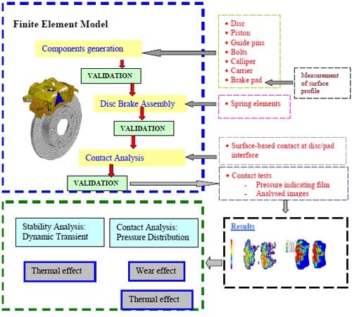
Figure 1. Overall simulation scheme.
Development and Validation Process of an FE Model
This section will describe in detail the development and validation process of a disc brake model throughout this research. The first validation stage is using modal analysis, in which the natural frequencies and mode shapes will be compared with the experimental results. It has two levels of validation, namely, components and assembly. The second validation stage uses contact analysis in which static contact pressure distributions at piston and finger pads, between simulated and measured are compared. There are a number of considerations that should be taken into account in order to model disc brake components and assembly, and simulate contact. These considerations are given in the subsequent sections. Chen et al (2003b) put forward a systematic way of carrying out testing and validation from an experimentalist’s point of view.
Construction of a Disc Brake Model
Two commercial software packages are employed in order to generate the disc brake model and to simulate different mechanical behaviour. A software package called MSC PATRAN R2001 is utilised to generate elements and nodes of the disc brake. The advantages of using this software include the ease of changing one element type to another, e.g., a linear 8-node solid element (C3D8) to a quadratic 20-node solid element (C3D20), specifying contact surfaces between the disc and pads, connecting components at interfaces with spring elements, and simplifying geometry modifications. The software is also capable of generating an input file that is compatible with ABAQUS v6.4, which will then be used to perform subsequent analyses such as modal analysis, contact analysis and the complex eigenvalue analysis.
A detailed 3-dimensional finite element (FE) model of a Mercedes solid disc brake assembly is developed. Figure 2(a) and 2(b) show the Liverpool rig of a real disc brake of floating calliper design and its FE model respectively. The FE model consists of a disc, a piston, a calliper, a carrier, piston and finge
r pads, two bolts and two guide pins. A rubber seal (attached to the piston) and two rubber washers (attached to the guide pins) are not included in the FE model. Damping shims are also not present since they have also been removed in the squeal experiments. The FE model uses up to 8350 solid elements and approximately 37,100 degrees of freedom (DOFs). This figure excludes the spring elements that have been used to connect disc brake components other than between the disc and pads.
The disc, brake pads, piston, guide pins and bolts are developed using a combination of 8-node (C3D8) and 6-node (C3D6) linear solid elements while the other components are developed using a combination of 8-node (C3D8), 6-node (C3D6) and 4-node (C3D4) linear solid elements. Element types in the brackets show the notation in ABAQUS nomenclature. Details for each of the components are given in Table 1.
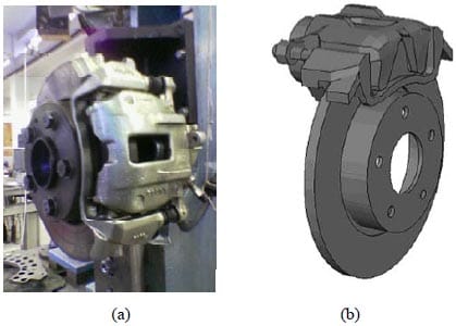
Figure 2. Disc brake assembly; (a) an actual disc brake (b) FE model.
Since the contact between the disc and the friction material surfaces is crucial, realistic representation of those interfaces should be made. The friction material has a rougher surface and is low in Young’s modulus than the disc, which has quite a smooth and flat surface, and is less prone to wear. Therefore in this work, actual surfaces at macroscopic scale of piston and finger pads are considered and measured. A Mitutoyo linear gauge LG-1030E and digital scale indicator are used to measure and provide reading of the surface respectively as shown in Figure 3. The linear gauge is able to measure surface height distribution ranging from 0.01mm up to 12 mm.
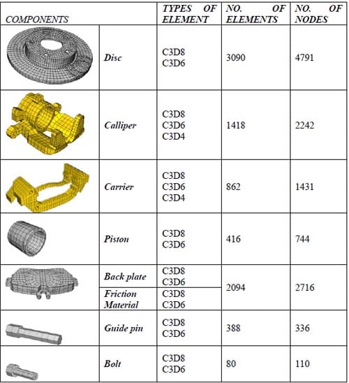
Table 1. Description of disc brake components.
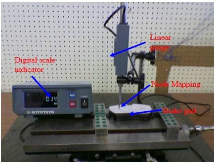
Figure 3. Arrangement of tools for surface measurement.
Prior to the measurement, the back plate must be flat and level. This can be confirmed by taking four measurement points at both pad abutments and the indicator should show similar height position. Node mapping, as shown in Figure 3, is required so that surface measurement can be made at particular positions, which are nodes of the FE model. By doing this, information that is obtained in the measurement can be used to adjust the coordinates of the piston and finger pad nodes in the brake pad interface model. There are about 227 nodes at the piston pad interface and 229 nodes at the finger pad interface. Since measurement is taken manually, it takes about two and half hours to complete this for a single pad. In this work, three pairs of brake pads (6 pieces) are measured, in which one pair of them are worn while the rest are new and unworn. All the brake pads are from the same manufacturer. Thus, it is assumed that the global geometry and material properties of the brake pad are the same. Upon completion of the modelling, all the disc brake components must be brought together to form an assembly model. Contact interaction between disc brake components is represented by linear spring elements (SPRING 2 in the ABAQUS nomenclature) except for the disc/pads interface where surface-to-surface contact elements are employed. This selection is due to the fact that contact pressure distributions at the disc/pad interface are more significant than at the contact interfaces of other components.
Figure 4 shows a schematic diagram of contact interaction that has been used in the disc brake assembly model. A rigid boundary condition is imposed at the boltholes of the disc and of the carrier bracket, where all six degrees of freedom are rigidly constrained in the rig.
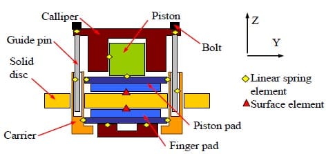
Figure 4. Schematic diagram of contact interaction in a disc brake assembly.
Modal Analysis
The experimental study of structural vibration has made significant contributions to better understanding of vibration phenomenon and for providing countermeasures in controlling such phenomenon in practice. Typically, experimental observations always have two-fold objectives (Ewins, 1984):
- Determining the nature and vibration response levels
- Verifying theoretical models and predictions
The first objective is referred to as a test where vibration forces or responses are measured during a structure’s normal service or operation while the second is a test where the structure or component is vibrated with a known excitation. The second test is much more closely carried out under controlled conditions and this type of test is nowadays known as modal testing or experimental modal analysis (EMA). There are two different methods of comparison available to verify a theoretical model over EMA. They are a comparison in terms of response properties and modal properties. Although response properties of a tested structure can directly be produced in EMA, it is less convenient for some finite element software packages when it comes to generate frequency response function (FRF) plots. Furthermore, comparisons of modal properties are perhaps most common and convenient in the current practice where natural frequencies and mode shapes (either graphical or numerical) are used to obtain correlation between predicted and EMA results.
In this work, experimental modal analysis that was conducted by James (2003) was utilised to verify the developed FE model. Natural frequencies and graphical mode shapes obtained in the experiments are used to compare with the finite element results. Comparisons are made at two levels, namely, models of disc brake components and an assembly model. Firstly, FE modal analysis is performed at components level where the dynamic behaviour of disc brake components in the free-free boundary condition is captured. The second stage is to perform FE modal analysis on the disc brake assembly where the disc and the carrier are mounted to the knuckle. A certain level of brake-line pressure is applied to the stationary disc brake. During the analysis a tuning process (also known as model updating) is required in order to reduce relative errors between the predicted and experimental results. Normally, material properties, such as density and spring stiffness, are tuned or adjusted for disc brake components and assembly models respectively in order to bring closer predicted natural frequencies to the experimental data.
All the components are firstly simulated in free-free boundary condition and there are no constraints imposed on the components. Natural frequencies up to 9 kHz are considered since this study takes into account squeal frequencies between 1~ 8 kHz. The finite element model of the disc is validated by the authors and compared with the experimental data while the material data of the other components were validated and provided by an industry source. It is always desirable to validate all the components at once. This has not been done due to limitation in the equipment and tools available in the laboratory. It is thought that laser vibrometers can capture natural frequencies and mode shapes more accurately, as no contact with the components is needed. This can reduce errors in measuring dynamic behaviour of the components, compared with using accelerometers, which need to be attached to the components.
For the free-free boundary condition of the brake disc, a number of modes for up to frequencies of 9 kHz are extracted and captured. There are various mode shapes exhibited in the numerical results. However, only nodal diameter type mode shapes are considered because they were found to be the dominant ones in the observed squeal events of this partic
ular disc brake. The calculated natural frequencies and mode shapes are given in Figure 5, which includes 2ND up to 7ND (nodal diameters). The number of nodal diameters is based on the number of nodes and anti-nodes appearing on the rubbing surfaces of the disc. Using standard material properties for cast iron the predicted frequencies are not well correlated with the experimental results. Hence tuning of the density and Young’s modulus is necessary to reduce relative errors between the two sets of results. Having tuned the material properties the relative errors are shown in Table 2 and the maximum relative error is – 0.5%. The new material properties after tuning are given in Table 3.
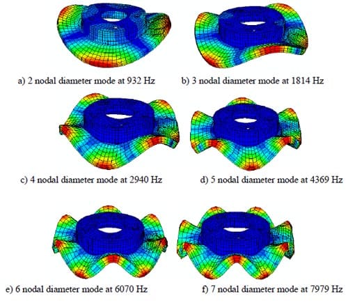
Figure 5. Mode shapes of the disc at free-free boundary condition.

Table 2. Modal results of the disc at free-free boundary condition
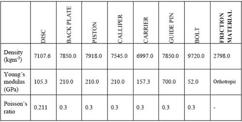
Table 3. Material data of disc brake components
The second stage of the methodology is to capture dynamic characteristics of the assembled model. The previous separated disc brake components must be now coupled together to form the assembly model. As discussed earlier in this chapter, a combination of linear spring elements and surface-to-surface contact elements are used to represent contact interaction between disc brake components and disc/pad interface, respectively. Table 4 shows details of disc brake couplings that are employed in the FE assembly model.
In the experimental modal analysis, a brake-line pressure of 1 MPa is imposed to the stationary disc brake assembly. A similar condition is also applied to the FE brake assembly model. In this validation, measurements are taken on the disc as it has a more regular shape than the other components. For the FE assembly model, spring stiffness values are tuned systematically as follows:
- At the interface of any two components that allow sliding between them the tangential spring constant is set at a very low stiffness, e.g., around 0.5 N/m. Example of this is between the guide pin and the carrier as given in Table 4.
- At the interface of any two components that restrict movement in any directions, e.g., between the bolt and the calliper arm, the spring constant is set a very high stiffness, e.g., around 1E+10 N/m.
- Any two interacting components that experience intermittent contact, e.g., the back plate and the piston, the spring stiffness is set around 1E+6 N/m.
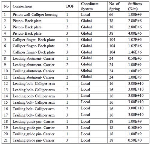
Table 4. Disc brake assembly model couplings
Once those spring constants are set, modal analysis is performed to obtain natural frequencies of the disc and their associated mode shapes. A comparison is made between predicted and experimental results of the disc. If there are large relative errors, the spring stiffness values for linking two components need to be adjusted or updated. This updating process is continued until the relative errors are reduced to an acceptable level. Since the process is performed based on the trail-and-error process, it takes a lot of time and requires engineering intuition to identify more influential springs and pick up appropriate spring constants.
After a number of attempts, good agreements between predicted and experimental results are achieved. Correlation between the two sets of frequencies that include 2ND up to 7ND of the disc is given in Table 5. From the table, it is found that the maximum relative error is – 5.2%. These predicted results are based on the spring stiffness values given in Table 4. Mode shapes of the FE assembly are described in Figure 6. The simulated FE modal analysis is able to predict two frequencies at 3-nodal diameter as obtained in the experiments, which are generated at 1730.1 Hz and 2151.1 Hz. While in the experiments these frequencies are found at 1750.7 Hz and 2154.9 Hz. The highest relative error is found on a 6-nodal diameter mode, for which the predicted frequency is 5837.1 Hz while the experimental frequency is 6159.0 Hz. The lower relative error is about – 0.1 % on the second 3-nodal diameter mode, for which the frequencies are 2151.1 Hz and 2154.9 Hz in theory and in experiments respectively. In this validation process, static friction coefficient (at pads/disc interface) also plays an important role to reduce the relative errors. It is found that static friction coefficient of µ = 0.7 give better correlation in the assembly model as described in Table 5.
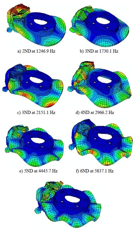
Figure 6. Mode shapes of the assembly model.
Contact Analysis
The third and final stage of the proposed methodology is to conduct experiments and simulations of contact pressure distributions under static application of the disc brake (that is, application of brake with no torque to or rotation of the disc). The experimental results will be used to confirm contact pressure distribution predicted in the FE model. In this section, brake pad models with real surface topography illustrated in Figures 7(a) ~ 7(c) are employed. The new and unworn pad pairs are used in order to confirm the measurements taken from the linear gauge and also to show the accuracy and reliability of the available tool.

Table 5. Modal results of the assembly measured on the disc
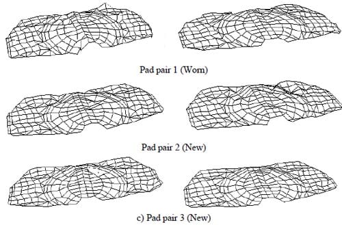
Figure 7. Surface topography at the piston pad (left) and finger pad (right).
In order to capture static contact pressure (stationary disc), Pressurex® Super Low (SL) pressure-indicating film, which can accommodate contact pressure in the range of between 0.5 ~ 2.8 MPa, is used. Pressure-indicating film is widely used to measure contact pressure distribution or surface roughness in the automotive industry. Tests conducted before and after a brake application often showed a noticeable difference between the measured pressure distribution at the disc and pads interface (Chen et al, 2003b).
In the current investigation, the films are tested under certain brake-line pressures for 30 seconds and then removed from the disc/pad interfaces. Figure 8 shows an example of pressure-indicating film before and after the contact testing. From the figure, the tested film only provides stress marks without revealing its magnitude. Topaq® Pressure Analysis system that can interpret the stress marks is then used. Configurations of the tested pad pairs are given in Table 6.

Figure 8. Pressure-indicating films before (left) and after (right) the static contact pressure testing.
Table 6. Configurations of tested pad
It is shown that contact pressure distributions for the worn pad (Pad pair 1) seem to be concentrated (red colour) at the outer border region of the pads, while zero pressure exists at the inner border region of the pads. It is also shown that contact pressure distributions of both the piston and finger pads are asymmetric. This might be due to irregularities in the surface topography of the friction material. Contact pressure
distributions of the worn pad are shown in Figure 9(a). The red colour shows the highest contact pressure. Areas in contact for the piston and finger pads are 1.436e-3m2 and 1.484e-3m2 respectively.
For the new and unworn pads, i.e., Pad pair 2 and Pad pair 3a that come from the same box and the same manufacturer, it is seen that they have different contact pressure distributions both at the piston and finger pad surfaces as shown in Figures 9(b) and 9(c). These variations are due to the surface topography as shown in Figure 7. It is also seen from figure 9(b) that contact pressures of Pad pair 2 are distributed more evenly than Pad pair 3a. There is contact at the trailing edge for Pad pair 2. But there seems to be a loss of contact in that region for Pad pair 3a. The areas of contact for the piston and the finger pads are 1.361e- 3 m2 and 1.069e-3 m2 respectively. From Figure 9(c), the contact pressure seems to be zero at the centre of the pads. Most of the highest contact pressures appear at the outer border of the pads. Areas in contact for Pad pair 3a are 8.090e-4m3 and 9.230e-4m2 for the piston and the finger pads respectively.
By applying different levels of brake-line pressure, the higher the pressure the bigger the contact areas should be generated. This is illustrated in Figure 9(d) where the areas of highest pressure are reduced significantly in comparison with Figure 9(c). It is also confirmed that the areas of contact for the piston and the finger pads are reduced to 6.370e-4 m2 and 6.857e-4 m2 respectively. This means a reduction of about 21% and 26% for the piston and the finger pads respectively.
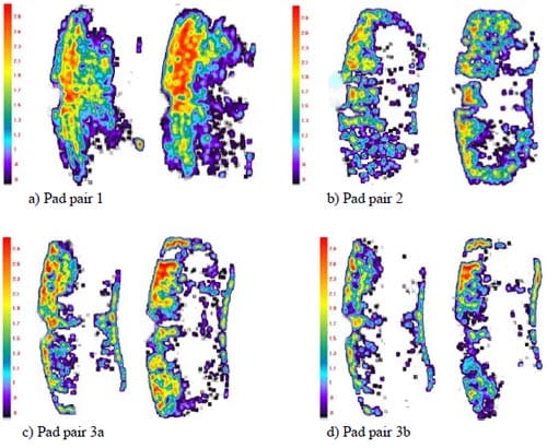
Figure 9. Analysed images of the tested pads: piston pad (left) and finger pad (right) in MPa. Top of the images are the leading edge.
In the FE contact analysis, the brake pad models are similar to those used in the contact tests. Now the real surface profile of the brake pads are considered in the sense that the surface profile information is incorporated in the FE model of the brake pad surface by adjusting its surface coordinates in the normal direction. Similar configurations of the test are also adopted in order to make comparison between the two sets of results, predicted versus experimental.
The first contact simulation is performed on the worn pad or Pad pair 1 at a brake-line pressure of 2.5 MPa. It can be seen in Figure 10(a) that the areas in contact are almost the same as those found in the experiment. Predicted contact areas in the contact analysis are 1.441e-3m2 and 1.784e-3m2 for the piston and the finger pads respectively. The results suggest that there is fairly good agreement between the two as illustrated in Figure 11. The contact area of the piston pad seems closer to the experimental one, compared with the finger pad.
The second contact simulation is done for Pad pair 2, which is subjected to the same brake-line pressure. From Figure 10(b) the contact pressure seems to be biased towards the outer radius of the pads. These patterns are most likely to be the same for those obtained in Figure 9(b). In the simulation it is found that the contact areas for the piston pad are 8.476e- 4m2 and for the finger pad is 8.131e-4 m2. These contact areas are smaller than those measured in the experiments. However, quite reasonable correlations against the experimental results are obtained especially at the finger pad as described in Figure 11.
The third contact analysis is simulated for Pad pair 3a, subjected to the same brake-line pressure. Predicted areas of the highest contact pressure are in good agreement with the experimental results. Contact pressure distribution of Pad pair 3a is illustrated in Figure 10(c). For Pad pair 3a, predicted contact areas are 1.046e-3 m2 and 1.020e-3 m2 for the piston and the finger pads respectively. It can be seen from Figure 11 that the difference in the finger pad is small while there is a quite large difference at the piston pad. However, overall, fairly good agreement is achieved between predicted and experimental results.
The last contact analysis is similar to the third except under a different brake-line pressure of 1.5 MPa applied to the assembly model. The predicted areas in contact should be smaller than those predicted in the third analysis and are shown in Figure 10(d). Once again, good correlations are achieved between predicted and experimental results in terms of areas of the highest contact pressure. The locations of different levels of the contact pressure distribution are almost identical to the experimental one. In the contact simulation, it is predicted that the contact areas of the piston pad and the finger pad are 5.943e-4 m2 and 6.860e-4 m2. These values are nearly the same as those measured in the experiment. Figure 11 shows that there are small differences in the contact area for both the piston and the finger pads.
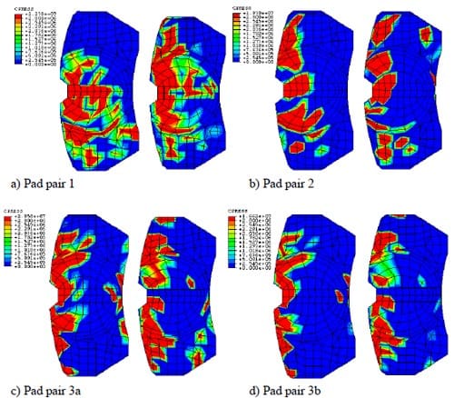
Figure 10. Predicted contact pressure distribution: piston pad (left) and finger pad (right) in Pascal. Top of the diagrams are the leading edge.
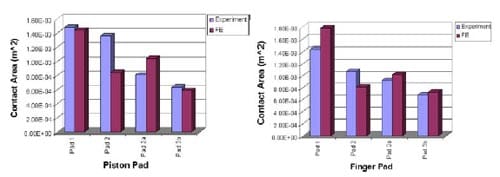
Figure 11. Comparison between experiment and FE analysis in the contact area.
Contact Pressure Distributions
At the contact interface of disc and brake pads, friction induces wear and heat during braking applications. Wear is one of the distinct aspects of brake systems that influence the contact pressure distribution, and itself is affected by the surface roughness of the components in sliding contact. Temperature is another distinct aspect and it normally rises up at some local area and thermal deformation of these areas occurs. Due to thermal deformation, the pressure distribution is also affected. Thermal and mechanical deformations affect each other strongly and simultaneously. This section looks into the effects of wear and temperature on contact pressure distributions.
Wear Effects
When two solid bodies are rubbed together they experience material removal, i.e., wear. In engineering applications the wear depth is a function of normal pressure, sliding distance and specific wear coefficient and other factors. Rhee (1970) in his study showed that the wear rate of most friction materials could be given as follows:
where ΔW is the wear volume, F is the contact force, v is the sliding speed, t is the time and k is the wear constant which is a function of the material and temperature. a, b and c are constants that should be determined experimentally and c is usually close to unity. This original formula however cannot be used in the present investigation. Since mass loss due to wear is directly related to the displacements that occur on the rubbing surface in the normal direction, Rhee’s wear formula is then modified as:
where Δh is the wear displacement, P is the normal contact pressure, Ω is the rotational disc speed (rad/s), r is the pad mean radius (m) and a, b and c are all constants which remain to be determined. In incorporating wear into the FE model, the methodology that was proposes by Podra et al (1999) and Kim et al (2005) is adopted in this work. Bajer et al (2004) also performed wear simulation
particularly for a disc brake. They used ABAQUS v6.5 and adopted a very simple wear model, i.e., a function of wear rate coefficient and contact pressure. On the other hand, Abu-Bakar et al (2005a) simulated wear progress over time using Equation (2) and assumed all constants were unity. In simulating wear, contact analysis is firstly performed in order to determine the normal contact pressure generated at the piston and the finger pads interface. Using Equation (2), wear displacements/depths are calculated based on the following parameters:
- Predicted contact pressure generated in the contact analysis, P
- Sliding time, t
- Specific wear rate coefficient, k
- Pad effective mean radius, r
- Rotational speed, Ω
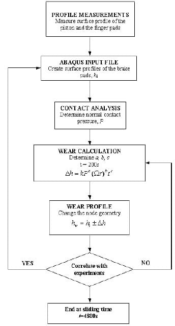
Figure 12. Flow chart of proposed wear simulation
As a case study, Pad pair 2 in Table 6 is used to observe wear evolution on the brake pad interface. In the wear analysis, a rotational speed is maintained at 6 rad/s and the total braking time is set to 4800s (8 minutes). The seemingly short duration of wear tests is due to a numerical consideration. In the wear formula of Equation (2), the duration of wear, t, must be specified. The longer the duration of wear, the more the dimensional loss and the greater change of the contact pressure. However, if t is too big, there will be numerical difficulties in an ABAQUS run. It has been found through trial-and-error that t = 200 s gives reasonably good results and good efficiency. Consequently a simulation of 80-minute wear means twenty-four ABAQUS runs. In line with this numerical consideration, wear tests have not lasted for numerous hours as normally done in a proper wear test or a squeal test. In theory, however, numerical simulations of wear may cover an arbitrary length of time. A constant specific wear rate coefficient is assumed for all braking applications and is set to k = 1.78e- 13m3/Nm (Jang et al, 2004) and the effective pad radius is r = 0.11m. Then, based on the calculated wear displacements at steady state, a new surface profile for the piston and the finger pads is created. Figure 12 shows the overall procedure of wear simulation that has been used by the authors.
During this wear calculation all constants in Equation (2) need to be determined. Having simulated for various values of constants a, b and c, it is found that the wear formula below gives reasonably good results.
In Equation (3), P’ is the maximum allowable braking pressure (8MPa for a passenger car) and k0 = 2.9 x 10⁻⁷m3. Figures 13 and 14 show measured and predicted static contact pressure distributions at the piston and finger pads, respectively. It can be seen that most locations of the highest contact pressure (in red colour) predicted are at the outer region of the brake pads and these are almost identical to the measured data shown in Figure 13. It is also seen that areas in contact increase as braking duration approaches 80 minutes described in Figure 15. From the figure, the initial contact areas are predicted as about 7.0e-4 m2 for both pads and then are predicted as much as 2.9e-3 m2 in the final stage of braking duration. This is an increase by more than four folds.
Due to wear progress, it is found from the FE analysis that the surface profile of the brake pads becomes smoother after 80 minutes of wear, as shown in Figures 16(a) and 16(b). As a result, greater areas of the brake pads come into contact with the disc surface, as also illustrated in Figures 13 and 14. Graphs in Figure 16 are axial coordinates of the nodes that form the circumferential centre lines of the pads. It is shown that at the early stage of braking application, i.e., within 10 – 20 minutes, the axial coordinates change slightly overall in comparison with the new (unworn) brake pads. Having completed 80 minutes of braking application the surface height seems to level off and hence implies that some initial rough patches have been worn out to form smoother ones.
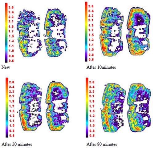
Figure 13. Measured contact pressure distribution: piston pad (left) and finger pad (right) in MPa. Top of the diagrams are the leading edge.
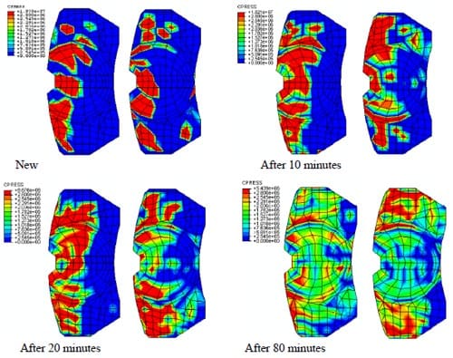
Figure 14. Predicted contact pressure distribution: piston pad (left) and finger pad (right) in Pascal. Top of the diagrams are the leading edge.
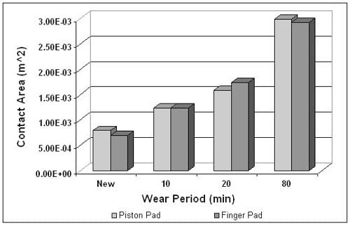
Figure 15. Predicted contact area for different braking application.
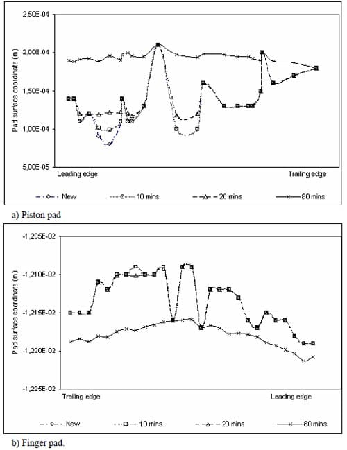
Figure 16. Predicted surface profile due to wear.
Thermal Effects
In a disc brake system, the brake pads are pressed against the disc in order to generate friction and therefore to slow down the vehicle. Once friction occurs, it induces a large amount of heat in the system. Therefore, thermal effects should be one of the most important aspects, which is likely to affect squeal generation in a disc brake system. Due to the complex phenomenon of heat transfer and the difficulty of numerical modelling, thermal effects have largely been ignored in the past research into disc brake squeal. However, there were a few researchers who studied thermal characteristics in brakes for purposes other than studying brake squeal in the past. Day and Newcomb (1984) investigated the friction-generated heat energy dissipated from the contact interface. Brooks et al (1993) looked into the brake judder phenomena by using thermo-mechanical finite element model. Kao et al (1994) studied thermo-elastic instability of disc brake system. Qi et al (2004) investigated temperature distributions at the friction interface. Recently, Triches et al (2008) and Hassan et al (2008) incorporated thermal effects in complex eigenvalue analysis to investigate instability of the disc brake assembly.
There are two aspects of thermal effects, namely, thermal deformation and temperature dependence of material properties. Take contact as an example. If thermal deformation is considered, then the contact area changes and pressure distribution also becomes different. As mentioned before, thermal deformation effects are considered in the present work and thermal analysis is implemented in the baseline model. Therefore, it requires the use of elements with both temperature and displacement degrees of freedom. The elements of disc and brake pads are meshed with C3D6 (solid 3-dimensional 6-nodes element) and C3D8 (solid 3-dimensional 8-nodes element) in the baseline disc brake finite element model. These elements are now replaced by C3D6T and C3D8T, which include the temperature degree of freedom. However, there is a limitation of ABAQUS software package regarding the element types. Specifically C3D8T is not available in ABAQUS/Standard version but is available in ABAQUS/Explicit version. There are two ways to deal with this problem: either creating a new FE model using those elements available in an ABAQUS/Standard version that allows thermal analysis or using ABAQUS/Explicit version instead. The former approach is considered a very difficult task and time-consuming. On the other hand, heat transfer is a transient process and as a result temperature varies with time. Therefore, dynamic transient analysis in ABAQUS/Explicit version is considered a more suitable
analysis method to simulate the squeal generation under thermal loading and therefore the latter approach is adopted.
In order to determine the temperature distribution in a medium, it is necessary to solve the appropriate form of heat transfer equation. However, such a solution depends on the physical conditions existing at the boundaries of the medium and on conditions existing in the medium at some initial time. To express the heat transfer in the disc brake model, several thermal boundary conditions and initial condition need to be defined. As shown in Figure 17, at the interface between the disc and brake pads heat is generated due to sliding friction, which is shown in blue colour. In this work, it is assumed that all the mechanical energy is converted into thermal energy. Al-Bahkali and Barber (2006) noted that the heat flux due to friction could be expressed as:
where µ is the friction coefficient, V is the sliding velocity of the disc and p represents the contact pressure at the interface.
For the exposed region of the disc and brake pads, it is assumed that heat is exchanged with the environment through convection. Therefore, convection surface boundary condition is applied there (shown in red colour in Figure17). This can be expressed as:

where h is convection heat transfer coefficient, k is thermal conductivity, and T∞ is atmosphere temperature and T(0,t) is the temperature at that boundary denoted by x = 0.
Finally, at the surface of the back plate, adiabatic or insulated surface boundary condition is used and shown in black colour in Figure 17. This can be expressed as
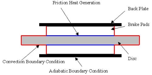
Figure 17. Boundary Condition of Thermal Analysis.

which means there is no heat transfer through the back plate into other disc brake components. This simplification removes the need to define the convection surface boundary condition of the exposed regions of the other components and is mainly a numerical consideration. Lin (2001) and Al-Bahkali and Barber (2006) used the same boundary conditions in their models. This simplification should be sufficient for short braking application where heat can hardly propagate far when squeal may occur already. It should also be noted that Equations (5) and (6) describe one-dimensional heat transfer for the sake of explanations and three-dimensional heat transfer is actually simulated in the authors’ research. The initial condition of the model is 20oC at every node of the disc and brake pads. The atmosphere temperature is also 20oC all the time.
Table 7 lists the thermal properties of the disc and brake pads and all these data are from Lin (2001). However, it turns out that using those appropriate values of thermal properties leads to exceedingly long computing time. A typical example of thermal analysis of the disc brake system takes a few weeks to finish. To overcome this problem, Choi and Lee (2003) used a value of specific heat that is much lower than the realistic value and found that much faster convergence to the steady state in the transient thermo elastic analysis could be achieved. Therefore, a much smaller value of specific heat capacity (20 J/kg K) is also adopted here instead.
A comparison is made between the contact pressure distributions with and without thermal effects. Figure 18 is the results of the contact pressure distribution with thermal effects. Figure 19 shows the contact pressure distribution without thermal effects. These results are obtained at Ω = 100 rad/s and P = 1 MPa. Comparing these two figures, the pressure distribution is different. The FE model with thermal effects shows that the contact pressure at the piston pad is spreading towards the leading edge, compared with the trailing edge for the FE model without thermal effects. For the finger pad, it shows that a larger contact area is established at the trailing edge with the thermal effects, compared with the FE model without thermal effects. The contact pressure is also higher in the model with thermal effects, which is 10.67 MPa, than the model without thermal effects, which is 6.83 MPa. Figures 20 and 21 are another example with Ω = 50 rad/s and P = 1 MPa. These two figures also show that the contact pressure at the piston and the finger pad is higher with the inclusion of thermal effects than the model without thermal effects. Distributions of contact pressure are also seen significantly different between the two models.

Table 7. Material thermal properties data of disc and brake pads
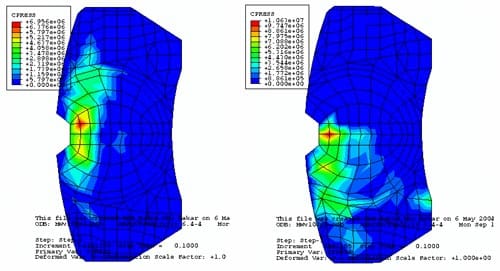
Figure 18. Pressure distribution with thermal effects in 100 rad/s and 1 MPa.
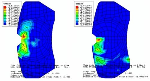
Figure 19. Pressure distribution without thermal effects in 100 rad/s and 1 MPa.
Vibration Analysis
There are two major numerical methods used in the studies of brake noise by researchers, namely, complex eigenvalue analysis and dynamic transient analysis. The advantages and limitations of both methods were commented by Mahajan et al (1999) and Ouyang et al (2005). In recent years, the dynamic transient analysis is gradually gaining popularity. A number of researchers pioneered this approach in their studies of squeal behaviour (Chargin et al, 1997, Hu and Nagy, 1997, Hu et al, 1999, Mahajan et al, 1999). Massi and Baillet (2005), Abu-Bakar and Ouyang (2006), Massi et al (2007) and Abu-Bakar et al (2007) furthered this approach. However, none of them considered thermal effects. Dynamic transient analysis in ABAQUS v6.4 is the approach used in this investigation into the vibration of the finite element disc brake model. ABAQUS uses central difference integration rule together with the diagonal lumped mass matrices. The following finite element equation of motion is solved:

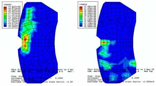
Figure 20. Pressure distribution with thermal effects in 50 rad/s and 1 MPa.
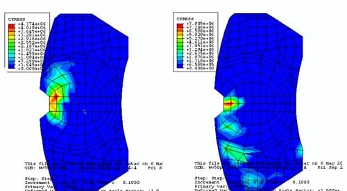
Figure 21. Pressure distribution without thermal effects in 50 rad/s and 1 MPa.
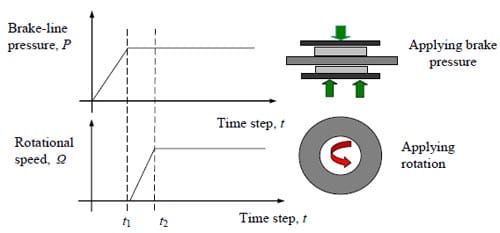
Figure 22. Time history of brake-line pressure and rotational speed.

where the superscripts (t – 0.5Δt) and (t + 0.5Δt) refer to mid-increment values. Since the central difference operator is not self-starting because of the mid-increment velocity, the initial values at time t = 0 for velocity and acceleration need to be defined. In this case, both values are set to zero as the disc is stationary at time t = 0.
T
he time history of the brake-line pressure and rotational speed are used for describing operating conditions of the disc brake model, as shown in Figure 22. At the first stage, a brake pressure is applied gradually until it reaches t1 and then it becomes constant. The disc starts to rotate at t1 and gradually increases up to t2. Then the rotational speed becomes constant too.
As a case study, two different operating conditions are considered in order to observe squeal behaviour in the disc brake assembly. The objective of this investigation is to reveal how thermal aspects affect squeal behaviour. Thus, a comparison between the disc brake model with and without thermal effects is made in this section. Figures 23 and 24 show the results of disc brake model with thermal effects at Ω = 50 rad/s and P = 1 MPa. Figure 25 and Figure 26 show the results from the model without thermal effects. From these figures, it is found that the vibration amplitude for the model with thermal effects is higher than the model without thermal effects. Moreover, the patterns of vibration of both examples are also different. However, the highest frequency components in these examples both are around 1200 Hz. Other examples are shown in Figures 27, 28, 29 and 30. The operational conditions are Ω = 50 rad/s and P = 0.5 MPa. The vibration amplitude also increases in the model with thermal effects compared with the results from the model without thermal effects. The highest frequency components both are around 1400 Hz this time. All these examples indicate that thermal effects do affect the vibration level of disc brake system and therefore are very likely to affect the squeal generation. Therefore, it would be worthwhile to include thermal effects in the prediction of disc brake squeal.
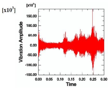
Figure 23. Time history of acceleration at a particular node with thermal effects (50 rad/s and 1 MPa).
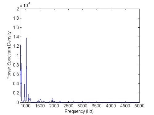
Figure 24. Frequencies after converting from time domain with thermal effects (50 rad/s and 1 MPa).
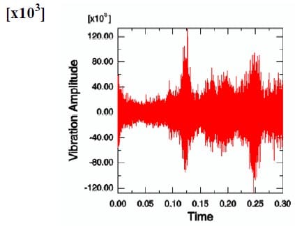
Figure 25. Time history of acceleration at a particular node without thermal effects (50 rad/s and 1 MPa).
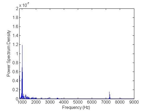
Figure 26. Frequencies after converting from time domain without thermal effects (50 rad/s and 1 MPa).
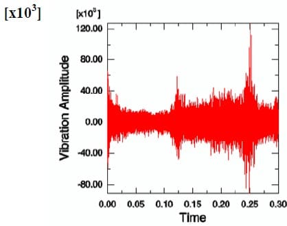
Figure 27. Time history of acceleration at a particular node with thermal effects (50 rad/s and 0.5 MPa).
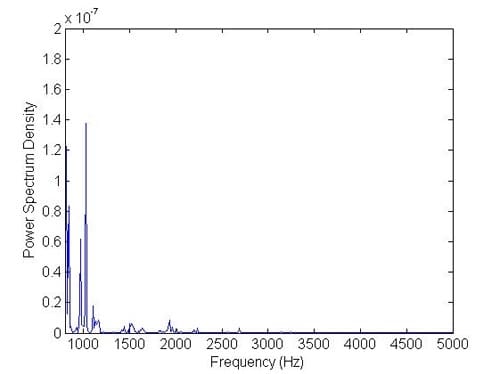
Figure 28. Frequencies after converting from time domain with thermal effects (50 rad/s and 0.5 MPa).
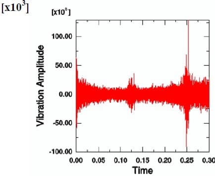
Figure 29. Time history of acceleration at a particular node without thermal effects (50 rad/s and 0.5 MPa)
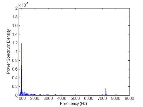
Figure 30. Frequencies after converting from time domain without thermal effects (50 rad/s and 0.5 MPa).
Conclusion
This chapter outlines recent studies into car disc brake squeal conducted at the University of Liverpool since 2004. The focus is on the numerical analysis using the finite element method. The simulation results are supported with measured data in order to verify predictions. An improved numerical methodology is presented by considering three-validation stages, namely, modal analysis at component and assembly levels and verification of contact analysis. Prior to that, a realistic surface roughness of the brake pad at macroscopic level is considered in the finite element model instead of assuming a smooth and perfect surface that has been largely adopted by most previous researchers. These two aspects have brought about significant improvement to the validation as well as analysis. Wear and thermal effects are other distinct aspects of disc brakes that influence contact pressure distributions and squeal generation in a disc brake assembly and they are also included in the current investigation. Transient analysis of disc brake vibration using a large FE model that includes thermal effects is carried out for the first time.
Acknowledgements
Some of the work reported in this chapter has been financially supported by TRW Automotive, Sensor Products LLC and Universiti Teknologi Malaysia. A number of people have helped this work at Liverpool, notably Dr S. James, Dr Q. Cao and Dr H. Tuah. Their contributions are gratefully acknowledged. Dr Tie Li of Ford at Basildon and Dr Frank Chen of Ford at Dearborn have kindly provided some papers.
REFERENCES
- ABAQUS Manual Version 6.4. (2003). Rhode Island, USA: Hibbitt, Karlsson & Sorensen, Inc.
- Abendroth, H., & Wernitz, B. (2000). The integrated test concept: dyno-vehicle, performance-noise. SAE Technical Paper 2000-01-2774.
- Abu-Bakar, A.R., & Ouyang, H. (2004). Contact pressure distribution by simulated structural modifications. In: Barton, D. C., Blackwood, A. Proceedings of IMechE International Conference- Braking 2004. UK: Professional Engineering Publishing Ltd; 123-132.
- Abu-Bakar, A. R., Ouyang, H., Li, L., & Siegel, J. E. (2005a). Brake pad surface topography Part II: Squeal generation and prevention. SAE Technical Paper 2005-01-3935.
- Abu-Bakar, A. R., Ouyang, H., & Siegel, J. E. (2005b). Brake pad surface topography Part I: Contact pressure distributions. SAE Technical Paper 2005-01-3941.
- Abu-Bakar, A. R., & Ouyang, H. (2006). Complex eigenvalue analysis and dynamic transient analysis in predicting disc brake squeal. International Journal of Vehicle Noise and Vibration, Vol. 2, No. 2, 143-155.
- Abu-Bakar, A. R., Sharif, A., Rashid, M. Z. A., & Ouyang, H. (2007). Brake squeal: Complex eigenvalue versus dynamic transient analysis. SAE Technical Paper 2007-01- 3964.
- Abu-Bakar, A. R., & Ouyang, H (2008). A new prediction methodology of disc brake squeal using complex eigenvalue analysis. International Journal of Vehicle Design (in press).
- Akay, A. (2002). Acoustics of friction. Journal Acoustics Society of America, Vol. 111, No. 4, 1525-1548.
- Al-Bahkali, E. A., & Barber, J. R. (2006). Nonlinear steady state solution for a thermoelastic sliding system using finite element method. Journal of Thermal Stresses, Vol. 29, 153- 168.
- Bajer, A., Belsky, V., & Kung, S. (2004). The influence of friction-induced damping and nonlinear effects on brake squeal analysis. SAE Technical Paper 2004-01-2794.
- Bajer, A., Belsky, V., & Zeng, L. J. (2003). Combining a nonlinear static analysis and complex eigenvalue extraction in brake squeal simulation. SAE Technical Paper 2003- 01-3349.
- Blaschke, P., Tan, M., & Wang, A. (2000). On the analysis of brake squeal propensity using finite element method. SAE Technical Paper, 2000-01-2765.
- Brooks, P. C., Barton, D., Crolla, D. A., Lang A. M., & Schafer, D. R. (1993). A new approach to disc brake judder using thermomechanical finite element model. Proceedings of I.Mech.E., Paper No. C462/31/064.
- Chargin, M. L., Dunne, L. W., & H
erting, D. N. (1997). Nonlinear dynamics of brake squeal. Finite Elements in Analysis and Design, Vol. 28, 69-82. - Chen, F., Tan, C. A., & Quaglia R. L. (2003a). On automotive disc brake squeal. Part I: mechanisms and causes. SAE Technical Paper 2003-01-0683.
- Chen, F., Abdelhamid, M. K., Blashke, P., & Swayze, J. (2003b). On automotive disc brake squeal. Part III: test and evaluation. SAE Technical Paper 2003-01-1622.
- Chen, F., Tan, C. A., & Quaglia, R. L. (Eds.), (2003). Disc brake squeal: Mechanism, analysis, evaluation, and reduction/prevention. Warrendale, USA: SAE International.
- Choi, J., & Lee, I. (2003). Transient thermoelastic analysis of disk brakes in frictional contact. Journal of Thermal Stresses, Vol. 26, 223-244.
- Crolla, D. A., & Lang, A. M. (1991). Brake noise and vibration: The state of the art. Vehicle Tribology Leeds-Lyon Tribology Series, No. 18, 165-174.
- Day, A., & Newcomb, T. P. (1984). The dissipation of friction energy from the interface of annular disc brake. Proceedings of I.Mech.E., Paper No. 69/84.
- Dom, S., Riefe, M., & Shi, T. S. (2003). Brake squeal noise testing and analysis correlation. SAE Technical Paper 2003-01-1616.
- Eriksson, M. (2000). Friction and contact phenomenon of disc brakes related to squeal. PhD Thesis, Faculty of Science and Technology, Uppsala University, Sweden.
- Eriksson, M., Bergman, F., & Jacobson, S. (1999). Surface characterization of brake pads after running under silent and squealing conditions. Wear, Vol. 232, No. 2, 163-167.
- Ewins, D. J. (1984). Modal testing: theory and practice. Letchworth: Research Studies Press.
- Fieldhouse, J. D (2000). A study of the interface pressure distribution between pad and rotor, the coefficient of friction and calliper mounting geometry with regard to brake noise. In: Barton, D. C., Earle S Proceedings of the International Conference on Brakes 2000 Automotive Braking – Technologies for 21st Century. UK: Professional Engineering Publishing Ltd; 2000; 3-18.
- Fieldhouse, J. D., Ashraf, N., & Talbot, C. (2008). The measurement and analysis of the disc/pad interface dynamic centre of pressure and its influence on brake noise. SAE Technical Paper 2008-01-0826.
- Ghesquiere, H., & Castel, L. (1991). High frequency vibrational coupling between an automobile brake-disc and pads. Proceedings of I.Mech.E., Paper No. C427/11/021.
- Goto, Y., Amago, T., Chiku, K., Matsushima, T., & Ishihara, T. (2004). Experimental identification method for interface contact stiffness of FE model for brake squeal. In: Barton, D. C., Blackwood, A. Proceedings of IMechE International Conference- Braking 2004. UK: Professional Engineering Publishing Ltd; 143-155.
- Guan, D., & Jiang, D. (1998). A study on disc brake squeal using finite element methods. SAE Technical Paper 980597.
- Hammerström, L., & Jacobson, S. (2006). Surface modification of brake discs to reduce squeal problems. Wear, Vol. 261, 53-57.
- Hassan, M. Z., Brooks, P. C., & Barton, D. C. (2008). Fully coupled thermal-mechanical analysis of automotive disc brake squeal. Automotive Research Conference 2008, Paper No. 05AARC2008.
- Hohmann, C., Schiffner, K., Oerter, K., & Reese, H. (1999). Contact analysis for drum brakes and disk brakes using ADINA. Computers and Structures, Vol. 72, 185-198.
- Hu, Y., & Nagy, L. I. (1997). Brake squeal analysis by using nonlinear transient finite element method. SAE Technical Paper 971510.
- Hu, Y., Mahajan, S., & Zhang, K. (1999). Brake squeal DOE using nonlinear transient analysis. SAE Technical Paper 1999-01-1738.
- Ibrahim, R. A., Madhavan, S., Qiao, S. L., & Chang, W. K. (2000). Experimental investigation of friction-induced noise in disc brake system. International Journal of Vehicle Design, Vol. 23, Nos. 3-4, 218-240.
- Ioannidis, P., Brooks, P. C., & Barton, D. C. (2003). Drum brake contact analysis and its influence on squeal prediction. SAE Technical Paper 2003-01-3348.
- James, S. (2003). An experimental study of disc brake squeal. PhD Thesis, Department of Engineering, University of Liverpool, UK.
- Jang, H., Ko, K., Kim, S. J., Basch, R. H., & Fash, J. W. (2004). The effect of metal fibers on the friction performance of automotive brake friction materials. Wear, Vol. 256, 406-414.
- Kao, T. K., Richmond, J. W., & Moore, M. W. (1994). The application of predictive techniques to study thermo-elastic instability in braking. SAE Technical Paper 942087.
- Kim, N. M., Won, D., Burris, D., Holtkamp, B., Gessel, G. R., Swanson, & Sawyer, W. G. (2005). Finite element analysis and experiments of metal/metal wear in oscillatory contacts. Wear, Vol. 258, Nos. 11-12, 1787-1793.
- Kinkaid, N. M., O’Reilly, O. M., & Papadopolous, P. (2003). Review of automotive disc brake squeal. Journal of Sound and Vibration, Vol. 267, 105-166.
- Kung, S., Dunlap, K. B., & Ballinger, R. S. (2000). Complex eigenvalue analysis for reducing low frequency brake squeal. SAE Technical Paper 2000-01-0444.
- Kung, S., Steizer, G., Belsky, V., & Bajer, A. (2003). Brake squeal analysis incorporating contact conditions and other nonlinear effects. SAE Technical Paper 2003-01-3343.
- Lang, A. M., & Smales, H. (1983). An approach to the solution of disc brake vibration problems. Proceedings of I.Mech.E., Paper No. C37/83.
- Lee, Y. S., Brooks, P. C., Barton, D. C., & Crolla, D. A. (1998). A study of disc brake squeal propensity using a parametric finite element model. Proceedings of I.Mech.E., Paper No. C521/009/98, 191-201.
- Li, L. (2007). Preliminary investigation of contact pressure and squeal of a disc brake considering thermal effects. MPhil Thesis, Department of Engineering, University of Liverpool, UK.
- Liles, G. D. (1989). Analysis of disc brake squeal using finite element methods. SAE Technical Paper 891150.
- Lin, J. (2001). The study of thermal and stress analysis of the disc brake of motorcycle. MPhil Thesis, Department of Mechanical Engineering, National Taiwan University, Taiwan.
- Liu, W., & Pfeifer, J. (2000). Reducing high frequency disc brake squeal by pad shape optimisation. SAE Technical Paper 2000-01-0447.
- Mahajan, S. K., Hu, Y., & Zhang, K. (1999). Vehicle disc brake squeal simulations and experiences. SAE Technical Paper 1999-01-1738.
- Massi, F., & Baillet, L. (2005). Numerical analysis of squeal instability. International Conference on Emerging Technologies of Noise and Vibration Analysis and Control, NOVEM2005, 1- 10.
- Massi, F., Baillet, L., Giannini, O., & Sestieri, A. (2007). Brake squeal: Linear and nonlinear numerical approaches. Mechanical Systems and Signal Processing, Vol. 21, No. 6, 2374- 2393.
- Nack, W. V. (2000). Brake squeal analysis by finite elements. Journal of Vehicle Design, Vol. 23, Nos. 3-4, 263-275.
- Nishiwaki, M.R. (1990). Review of study on brake squeal. JSAE Review, Vol. 11, No. 4, 48– 54.
- Ouyang, H., Cao, Q., Mottershead, J. E., & Treyde, T. (2003a). Vibration and squeal of a disc brake: modelling and experimental results. Proceedings of I.Mech.E., Part D: Journal of Automobile Engineering, Vol. 217, 867-875.
- Ouyang, H., Mottershead, J. E., & Li, W. (2003b). A moving-load model for disc-brake stability analysis. Journal of Vibration and Acoustics, Vol. 125, No. 1, 53-58.
- Ouyang, H., Mottershead, J. E., Brookfield, D. J., James, S., & Cartmell, M. P. (2000). A methodology for the determination of dynamic instabilities in a car disc brake. International Journal of Vehicle Design, Vol. 23, Nos. 3-4, 241-262.
- Ouyang, H., Nack, W. V., Yuan, Y., & Chen, F. (2005). Numerical analysis of automotive disc brake squeal: a review. International Journal Vehicle Noise and Vibrations, Vol. 1, Nos. 3-4, 207-230.
- Podra, P., & Andersson, S. (1999). Simulating sliding wear with finite element method. Tribology International, Vol.
32, 71-81. - Qi, H. S., Day A. J., Kuan K. H., & Forsala, G. F. (2004). A contribution towards understanding brake interface temperatures. In: Barton, D. C., Blackwood, A. Proceedings of I.Mech.E., International Conference- Braking 2004. UK: Professional Engineering Publishing Ltd; 251-260.
- Rhee, S. K. (1970). Wear equation for polymers sliding against metal surfaces. Wear, Vol. 16, 431-445.
- Richmond, J. W., Smith, A. C., Beckett, P. B., & Hodges, T. (1996). The development of an integrated experimental and theoretical approach to solving brake noise problems. Advances in Automotive Braking Technology, Design Analysis and Material Developments, 3-23.
- Ripin, Z. B. M. (1995). Analysis of disc brake squeal using the finite element method. PhD Thesis, Department of Mechanical Engineering, University of Leeds, UK.
- Samie, F., & Sheridan, D. C. (1990). Contact analysis for a passenger car disc brake. SAE Technical Paper 900005.
- Sherif, H. A. (2004). Investigation on effect of surface topography of pad/disc assembly on squeal generation. Wear, Vol. 257, Nos. 7-8, 687-695.
- Soom, A., Serpe, C. I., & Dargush, G. F. (2003). High frequency noise generation from components in sliding contact: flutter instabilities including the role of surface roughness and friction. Tribology and Interface Engineering Series, Vol. 43, 477-485.
- Tamari, J., Doi, K., & Tamasho, T. (2000). Prediction of contact pressure of disc brake pad. JSAE Review, Vol. 21, 136-138.
- Tarter, J. H. (1983). Disc brake squeal. SAE Technical Paper 830530.
- Tirovic, M., & Day, A. J. (1991). Disc brake interface pressure distributions. Proceedings of I.Mech.E., Vol. 205, 137-146.
- Triches, M. J., Gerges, S. N. Y., & Jordan, R. (2008). Analysis of brake squeal noise using the finite element method: a parametric study. Applied Acoustics, Vol. 68, No. 2, 147- 162.
- Yang, S., & Gibson, R. F. (1997). Brake vibration and noise: review, comments and proposals. International Journal of Materials and Product Technology, Vol. 12, Nos.4–6, 496–513.
- Yuan, Y. (1996). An eigenvalue analysis approach to brake squeal problems. Proceedings of the 29th ISATA Conference Automotive Braking Systems, Florence, Italy.


