A New Prediction Methodology for Dynamic Contact Pressure Distribution in a Disc Brake
ABD RAHIM ABU BAKAR1, MOHD KAMEIL ABDUL HAMID2 & HUAJIANG OUYANG3
Abstract.
The dynamic contact pressure distribution in a disc brake system remains impossible to measure through experimental methods. This makes numerical analysis using the finite element method an indispensable alternative tool to its prediction. However, the finite element model must first be validated through appropriate analyses so that realistic predicted results can be obtained. This paper proposes and carries out a three-stage validation methodology: validating the dynamic aspect of each brake component and the brake assembly using modal testing data and the contact aspect using the experimental results of static contact pressure. A detailed 3-dimensional finite element model of an actual disc brake was developed. Brake pad surface topography is also taken into consideration. Good agreement is achieved between predicted and experimental results both in modal analysis and static contact pressure distributions. Once a validated model was obtained, contact analysis for dynamic condition of the disc brake is performed.
Key words: disc brake, dynamic contact pressure, surface topography, contact tests, modal analysis, finite element
1&2 Department of Aeronautic and Automotive Engineering, Faculty of Mechanical Engineering, Universiti Teknologi Malaysia, 81310 Skudai, Johor Darul Ta’zim. Email: [email protected]
3 Department of Engineering of Liverpool, L693GH, UK.
1.0 INTRODUCTION
Research on contact pressure distributions in a disc brake system has been carried out by a number of people. The parameter is now becoming essential to the brake research community especially to those who are predicting squeal noise using numerical methods of either the complex eigenvalue analysis or the dynamic transient analysis [1, 2]. To date, it is still impossible to measure dynamic contact pressure distributions through experimental methods. To the authors’ knowledge, the only experimental methods that have been used in measuring disc brake contact pressure distributions are the ball pressure method [3] and through a commercial pressure-sensitive film [4]. However, this measurement is limited to static contact pressure where the disc/ rotor pair is in a stationary condition. Contact pressure prediction by means of numerical methods was studied in [4-11]. There are several levels of complexity in disc brake models that have been developed in order to predict dynamic contact pressure distributions through numerical methods. For example, Samie and Sheridan [4] developed a 3-dimensional finite element model of brake pads. Ripin [6] only considered brake pads and a rigid surface of the disc in his 3-dimensional model. While Lee et al., [7] adopted a deformable disc, however the calliper and the carrier were not included in their model. Tirovic and Day [5], and Hohmann et al., [8] included a deformable disc with more brake components than those in [6,7]. Works that considered all disc brake components and used deformable-to-deformable surfaces of the disc and pads are in [9-11]. Even though various models have been reported, contact analysis should be carried out carefully in order to obtain more realistic results.
Amongst the afore-mentioned models, only those of [4] and [6, 7] were validated, through either contact analysis or modal analysis (but not both), whilst no mention of validation was made of the others. Ripin [6] and Lee et al. [7] validated their models, but only at one stage, i.e., at the components level. For complex eigenvalue analysis of disc brake squeal, some researchers have used FE models that were validated at the components and assembly level based on modal testing data, for example, in [12, 13]. The authors believe that validation through modal analysis at the components and assembly level is still not enough for better prediction of brake squeal as well as realistic dynamic contact pressure. Since the complex eigenvalue analysis largely depends on the contact pressure distribution [12-16], it is essential to develop a more realistic representation of the FE model. As stated before, static contact pressure can be obtained by experimental methods. This information provides another validation tool for the FE model.
In the past, all FE models assumed the presence of a smooth and flat disc/ pads interface. However, this is not true in actual disc brakes. Assuming a smooth and flat interface in a FE model leads to large discrepancy in predicted contact pressure results. The authors have measured brake pad surface topography and included this information in their FE model. Comparison of static contact pressure distributions will be made between a model that assumes a smooth and flat disc/pads interface and a model that considers real brake pad surface topography. The paper also attempts to produce a more realistic FE model that is validated through not only modal analysis but also contact analysis of static contact pressure distribution. Experiments on static contact pressure are carried out using pressure-indicating films and then these films are analysed by Topaq® Pressure Analysis System. These three stages form the authors’ validation methodology. Finally, contact pressure distributions are determined at a certain rotating speed and brake-line pressure.
2.0 STATIC CONTACT PRESSURE TEST
The tests were carried out using an in-house brake dynamometer at the University of Liverpool. In this work, a special film called Super Low pressureindicating film a product of Sensor Products LLC was employed. The film is capable of accommodating a local pressure in the range of between 0.5 – 2.8 MPa. For static contact pressure tests, the films need to be cut to the shape of the brake pads for them to be well positioned at the pads/disc interface. Brakeline pressure at a certain level was applied for about 30 second (with the disc being stationary) and then the films were removed. Stress marks appearing on the films indicate distributions of contact pressure.
It is essential to obtain both qualitative and quantitative features of static contact pressure distributions from the films. In doing so, the Topaq® Pressure Analysis System was used to scan the tested films and then analysed them so that both the magnitude and distribution of contact pressure can be obtained. The Topaq system is a post-process interpretive system that analyses pressure distribution and magnitude from a proprietary tactile transducer or from a pressure-indicating film [17]. In this study, two sets of brake pads are tested under a brake-line pressure of 2.5 MPa. Static contact pressure distributions at piston and finger pads are depicted in Figure 1 as optic
ally imaged and analysed.
3.0 FINITE ELEMENT MODEL
The finite element model in this work consists of a disc (rotor), piston and finger pads, a calliper, a carrier and a pair of guide pins. Damping shims are not included in order to reduce complexity of modelling. The model includes up to 8000 solid elements and approximately 37,200 degrees of freedom. The FE model is illustrated in Figure 2. Before contact analysis is conducted, modal analysis is firstly performed. The FE model is validated through two stages i.e., at disc brake components and assembly levels. By adjusting the Young’s modulus and the density of the disc [1, 6, 12-13], the numerical and experimental frequencies of the free-free disc become very close and are listed in Table 1. The material data of the other brake components comes from an industrial source and has been validated and is given in Table 2.
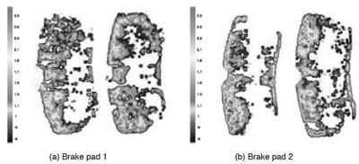
Figure 1 Analysed images of static contact pressure distributions at piston (left) and finger (right) pads

Table 1 Modal results of the disc at free-free boundary condition
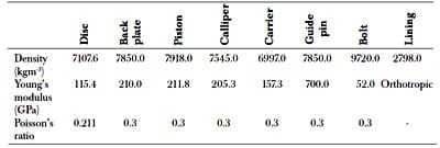
Table 2 Material properties of disc brake components
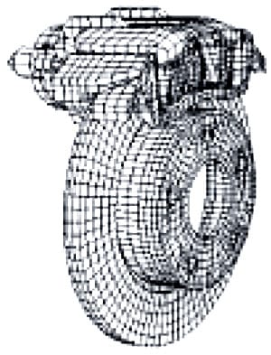
Figure 2 A disc brake FE model
Hammer tests were carried out on the disc bolted to the knuckle, during which a brake-line pressure of 1.0 MPa was applied [18]. In the FE model, all the disc brake components were brought together and contacts between the components are represented by a number of linear spring elements except for the disc/pads interface where surface elements were employed. Spring elements were tuned in order that frequencies between experimental and simulated results become very close as listed in Table 3.

Table 3 Modal results of the assembly model measured on the disc
In the past, brake pad surface was always modelled as a smooth and flat surface. However, an actual brake pad has an irregular or corrugated surface. Therefore, measurement on the actual brake pad surface should be made. The data then can be used to generate a more realistic topography of brake pads surface. In this work, a linear gauge LG–1030E from Mitutoyo was used for measuring the surface profile. Measurements were taken on locations that coincide with the pad surface nodes of the FE model. This information was used to adjust the coordinates of the corresponding nodes in the FE model. The contact analysis was performed for when the disc was stationary (static) and when the disc was rotating (dynamic). First, the static contact is simulated in order to validate the FE model where the simulated results were compared with the results obtained in the experiments. A comparison is also made for the model that assumes a smooth and flat disc/pads interface. Detailed results and discussion are described in the following section.
4.0 CONTACT ANALYSIS
In this paper the contact problem is modelled by using element-based surfaces and surface-based contact, and is analysed using small sliding interaction regime. The element-based surfaces are used owing to its advantages over the nodebased surfaces, i.e., more accurate results in contact pressure and contact stresses. For surface-based contact a master surface and a slave surface are required to form a contact pair. Meanwhile for small sliding the contact formulation assumes that the contact surfaces may undergo arbitrarily large rotations but that a slave node will interact with the same local area of the master surface throughout the analysis. This is suitable for the case of disc brake where the pads will interact with the same profile of the rotating disc surface. Convergence could also be easily obtained, compared with the finite sliding regime.
In the static contact analysis, a friction coefficient of µ = 0.65 is prescribed for the contact interface between the pads and the disc. Similarly, a brake-line pressure of 2.5 MPa, as applied in the experimental tests, was imposed on the top of the piston model and on top of calliper housing. The predicted results based on the perfect contact interface (Figure 3(a)) show that the contact pressure distributions are symmetrical for both the piston and the finger pads whereas the analysed images show differently. The simulated results of the brake pad 1 and brake pad 2 based on measured pad surface topography seem to provide more realistic results qualitatively as shown in Figures 3(b) and 3(c). Thus, good correlation is achieved between the simulated and experimental results for both brake pad 1 and brake pad 2. Comparison is also made in the contact area where it is shown that for real contact interface both brake pad 1 and brake pad 2 give quite close prediction to the experimental results whereas for the perfect contact interface there are large discrepancies between predicted and experiments. This comparison can be seen from Figure 4.
The numerical results suggest that good correlations at both brake components and assembly stage are still not sufficient to produce realistic results on static contact pressure distributions without considering brake pad surface topography. It is essential to note that the assumption of a smooth and flat surface is no longer valid if contact pressure distributions are a main aspect of an investigation.
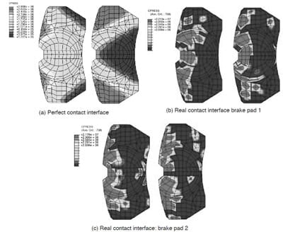
Figure 3 Simulation results of static contact pressure distributions at the piston (left) and finger (right) pads
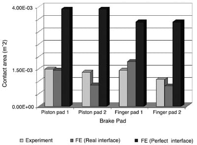
Figure 4 Comparison of contact area
Once a realistic FE model is obtained, contact analysis for dynamic condition of the disc brake is performed. A rotational speed of w = 6 rad/s and a brakeline pressure of p = 3.0 MPa were imposed on the disc brake. For a comparison, an FE model with a smooth and flat surface is also analysed. A kinetic friction coefficient of µk = 0.58 is used for the pads/disc interface. In the simulation two steps are required. Firstly, a brake-line pressure is applied to the disc brake and this will push the piston and finger pads towards the disc interface. Secondly, the disc is rotated at the aforementioned speed about its axial axis. Dynamic contact pressure distributions for three different brake pads surface topographies are shown in Figures 5(a)-5(c). There are big differences in dynamic contact pressure distributions between the model that has a smooth and flat contact interface and the models that consider brake pads surface topography. However, a similar trend is observed where all the contact pressure distributions tend to shift towards the leading edge, compared with the static contact pressure distributions. A comparison among those three brake pads shows that the model with a smooth and flat contact interface has a larger contact area compared with those two models that consider the pad surface topography, as described in Table 4. The apparent contact area (geometric area) of the pad is 0.0039m2.
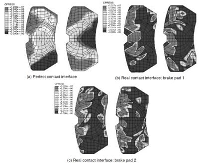
Figure 5 Simulation results of dynamic contact pressure distributions at the piston (left) and finger (right) pads. Top of the pads is the leading edge

Table 4 Predicted contact area of the brake pads of rotating disc
5.0 CONCLUSIONS
The objective of the paper to obtain dynamic contact pressure distributions of the disc brake is achieved. Prior to that, three stages of model validation are suggested and conducted, that is, the modal analysis for the brake components and brake assembly, and the contact analysis for static contact pressure distributions. In order to achieve a realistic representation of brake pads, measurements on the real brake pad surface profiles were carried out and interpreted. Static contact pressure tests were established as an FE model validation tool.
Good agreement between static contact pressure distributions and experimental results both qualitatively and quantitatively were achieved for the FE model that considers the real surface profile of brake pads, in comparison with the model with a smooth and flat contact interface that adopted by many researchers in the brake research community. Since contact pressure distributions are largely influenced by the local detail of the contact interface, a more refined FE model of the disc and brake pads should be built in order to obtain more realistic results. Given a better representation of brake components and assembly, current commercial software packages are capable of predicting more realistic results of contact pressure distributions.
ACKNOWLEDGEMENTS
The first author wishes to thank Dr Simon James of University of Liverpool for providing modal testing data, Dr Q. Cao of University of Aberdeen for helping with the tuning process, Sensor Products Inc. for supplying films and analysed images, and Universiti Teknologi Malaysia for sponsoring the first author.
REFERENCES
- Liles, G. D. 1989. Analysis of Disc Brake Squeal Using Finite Element Method. SAE Technical Paper 891150.
- Mahajan, S. K., Y. K. Hu, and K. Zhang. 1999. Vehicle Disc Brake Squeal Simulations and Experiences. SAE Technical Paper 1999-01-1738.
- Tumbrink, H. J. 1989. Measurement of Load Distribution on Disc Brake Pads and Optimization of Disc Brakes Using the Ball Pressure Method. SAE Technical Paper 890863.
- Samie, F., and D. C. Sheridan. 1990. Contact Analysis for a Passenger Cars Disc Brakes. SAE Technical Paper 900005.
- Tirovic, M., and A. J. Day. 1990. Disc Brake Interface Pressure Distributions. J. Automobile Engineering, Part D.205: 137 –146.
- Ripin, Z. B. M. 1995. Analysis of Disc Brake Squeal Using Finite Element Method. PhD. Thesis. Department of Mechanical Engineering, University of Leeds.
- Lee, Y. S., P. C. Brooks, D. C. Barton, and D. A. Crolla. 1998. A Study of Disc Brake Squeal Propensity Using Parametric Finite Element Model. Proceedings of IMechE International Conference on Noise and Vibration. Leeds, UK. 191 –201.
- Hohmann, C., K. Schiffer, K. Oerter, and H. Reese. 1999. Contact Analysis for Drum Brakes and Disk Brakes Using ADINA. Computers and Structures. 72: 185 – 198.
- Tamari, J., K. Doi, and T. Tamasho. 2000. Prediction of Contact Pressure of Disc Brake Pad. SAE Review. 21: 133 – 141.
- Rumold, W., and R. A. Swift. 2002. Evaluation of Disc Brake Pad Pressure Distribution by Multibody Dynamic Analysis. Proceedings of Braking 2002 on Vehicle Brakes. Leeds, UK. 75 –83.
- AbuBakar, A. R., and H. Ouyang. 2004. Contact Pressure Distributions by Simulated Structural Modifications. Proceedings of Braking 2004 on Vehicle Braking and Chassis Control. Leeds,UK.123-132.
- Ouyang, H., Q. Cao, J. E. Mottershead, and T. Treyde. 2003. Vibration and Squeal of a Disc Brake: Modelling and Experimental Results. J. Automobile Engineering, Part D. 217: 867-875.
- Goto, Y., T. Amago, K. Chiku, T. Matshushima, and Y. Ishihara. 2004. Experimental Identification Method for Interface Contact Stiffness of FE Model for Brake Squeal. Proceedings of Braking 2004 on Vehicle Braking and Chassis Control. Leeds, UK.143 –155.
- Nack, W. V. 2000. Brake Squeal Analysis by the Finite Element Method. Int. J. Vehicle Des. 23: 263- 275.
- Blaschke, P., M. Tan, and A. Wang. 2000. On the Analysis of Brake Squeal Propensity Using Finite Element Method. SAE Technical Paper 2000-01-2765.
- Kung, S. W., G. Stelzer, V. Belsky, and A. Bajer. 2003. Brake Squeal Analysis Incorporating Contact Conditions and Other Nonlinear Effect. SAE Technical Paper 2003-01-3343.
- Sensor Products LLC. 2005. https://www.sensorprod.com/topaq.html.
- James, S. 2003. An Experimental Study of Disc Brake Squeal. PhD. Thesis. Department of Engineering, the University of Liverpool


