Douglas Dierdorf, Ph.D., John Hawk, P.E.
Applied Research Associates Tyndall AFB, Florida
Air Force Research Laboratory
Materials and Manufacturing Directorate
Airbase Technologies Division
Tyndall AFB, Florida
Abstract
In response to incidents at munitions plants that have caused considerable equipment damage, production delays, and personal injuries, the Air Force Research Lab’s (AFRL) Fire Research Group at Tyndall Air Force Base has been working to invent a more effective deluge system capable of stopping high velocity fires caused by deflagration of explosives, propellants, and pyrotechnic materials. A detector has been developed that is one hundred times faster than the best detector on the market, and water velocity three times faster than the existing state of the art system has been achieved. In live fire experiments of up to four pounds of magnesium-Teflon pyrotechnic material, the AFRL deluge system put water on fires 36 inches from the spray head six milliseconds after detection and extinguished the fires in as little as 16 milliseconds. Compared to the NFPA requirement of 100 millisecond response from detection to initiation of water flow, and compared to 26 milliseconds from detection to water on fires for the best current deluge system, AFRL’s system offers the possibility of suppressing fires in facilities where ultra-fast burning materials are manufactured or handled.
Introduction
Losses in government and Department of Defense (DOD) contract facilities engaged in manufacturing, processing, handling, and demilitarization of ordnance containing propellants and pyrotechnic materials amounted to more than $9,500,000 in property damage and loss of seven lives during the period from 1988-1992, not including additional costs from lost production, accident investigations, legal expenses, etc.1 Many of these facilities require fire protection by ultra high speed fire suppression systems, defined in NFPA 152, Water Spray Fixed Systems for Fire Protection, as systems with a response time of 100 ms or less from detection of an energy source to water exiting the system nozzle(s). The 100 ms does not include the duration from water exiting the nozzles to water reaching the flame, which can add a significant amount of time to extinguishing a fast progressing fire. For many propellants, pyrotechnic materials, and aerosols, 100 ms is far too slow to prevent catastrophe.
In 1994 the U.S. Army Defense Ammunition Logistics Activity engaged the DOD Fire Research Group at the Air Force Research Laboratory (AFRL), Tyndall Air Force Base, Florida to design an ultra-high-speed fire suppression system with a faster response for use in ammunition plants. The Advanced Fire Protection Deluge System (AFPDS) was the result of those studies (Figure 1). The AFPDS consisted of 2.5 gal and 8 gal (10 L and 30 L) spherical tanks nearly filled with water and pre-charged with nitrogen to 500 psi, dual band UV/IR or IR/IR flame detectors, a 200-400 gal back-up water tank pressurized to 150 psi, and a controller. The spherical tanks were built to accommodate a very small explosive charge. Upon detection, a signal was sent by the controller to detonate the explosive charge in the spherical tanks and to open solenoid operated valves in the back-up water system. Detonation of the charge caused the internal pressure of the spherical tank to rise to about 1000 psi, forcing open a rupture disk on the tank and allowing water to be expelled through a spray nozzle at near 170 fps. The AFPDS reduced response time to about 8 ms (6 ms detection time and 2 ms initiation time) and put water on a fire 36 inches away from the spherical tanks in 18 ms. Close behind, back-up water reached the fire in about 130 ms. In 100 trials using ¼ to ½ pound samples of various pyrotechnic materials, most fires were extinguished by the initial water from the spherical tanks, and the back-up water was redundant.3
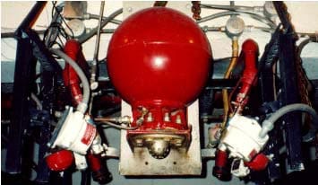
Figure 1.Advanced Fire Protection Deluge System (AFPDS)
Effective as the AFPDS was on most pyrotechnic materials, it was not fast enough to stop fires from the fastest burning materials, epitomized by MJU 32/38 magnesium-Teflon pyrotechnic flare material, so the Fire Research Group set out to improve on the AFPDS. A new photo-transistor-circuit flame detector was developed that cut detection time from 3-5 ms to less than 1 ms and was made less false alarm prone by using a mask that limited the field of view of the detector. Also, a new deluge system (Figure 2), the blast initiated deluge system (BIDS), was developed that could discharge water at near 500 fps. The heart of the BIDS consisted of a steel cone set inside a 16 gal steel cylinder. Filled with water, about 4 gal of water resided inside the cone and the other 12 gal on the outside. There was a small explosive charge fixed at the apex of the cone. Upon detection of a fire, the controller sent an electrical signal to the explosive detonator. Detonation of the charge caused a rapid rise in pressure inside the cone that forced the initial 4 gal of water out a plastic burst disk and on to the fire. Holes in the side of the cone allowed the 12 gal of follow-on water to flow through the cone and on to the fire. The BIDS reduced time from detection to water on the fire to 7-8 ms as compared to about 20 ms for the AFPDS and 130 ms or longer for solenoid activated systems. The BIDS extinguished 1 lb samples of MJU 32/38 in an average of 15 ms, and limited heat flux to a level significantly below the maximum allowed by Military Standard 398 (MIL-STD-398)4 even though the heat flux from an unsuppressed burn far exceeded those limits (Figure 3).
Though successful at suppressing even fast burning MJU 32/38 flare mixture, the Fire Research Group engineers were not completely satisfied with the narrow spray pattern produced by the BIDS, and they desired a system with more direct and follow-on water. A second generation BIDS was designed, built, and tested. Results of experiments for this second generation system are the primary focus of this paper.
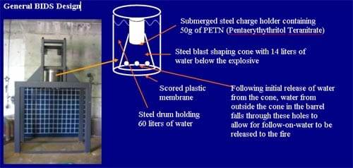
Figure 2. First Generation Blast Initiated Deluge System (BIDS) Test Platform.

Figure 3. Heat Flux Measured for Unsuppressed (left) and Suppressed (right) Burns of 1 lb of MJU 32/38 Flare Material.
2. Methods, Assumptions, and Procedures
To solve the narrow spray pattern problem, the spray cone was made bigger around a
t the base and shorter in height. The volume under the cone was increased from 4 to 4 ½ gal, and the total volume of the cylinder was increased from 16 to 20 gal (Figure 4). Instead of a flat seating surface at the apex of the cone where the explosive charge was mounted, a rounded surface was made to better match the angle of the cone andbetter distribute blast pressure. Explosive tiles were specially made to fit the roumounting surface (Figure 5). The tiles were a mixture of 50 g of explosive and Styrofoam. The Styrofoam was used to dilute the explosive, spreading the explosive ova larger volume, and to facilitate long term immersion of the explosive in water. Two different sizes of tiles were made, both having the same amount of explosive materiwith different amounts of Styrofoam. A larger Styrofoam to explosive ratio would distribute the explosive more thinly and cause a longer duration explosion with a lowpeak pressure as compared to the tiles with less Styrofoam. A larger test frame was constructed to increase the area of the table surface where the samples were placed, and heavier structural components were used so that the frame could be used repeatedly with little structural deformation from the reaction force of the blast (Figure 6).
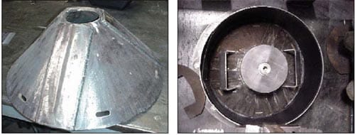
Figure 4. BIDS Cone (left). Cone Mounted in the Cylindrical Water Tank (right).
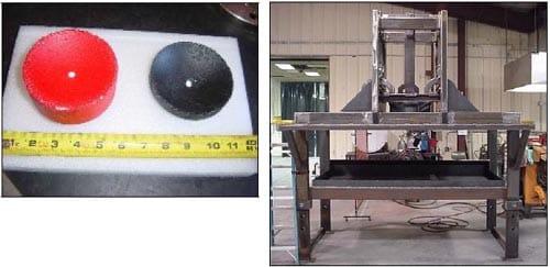
Figure 5. – Dilute Explosive Tiles and Figure 6. – BIDS Test Platform
A cylindrical liner of 80 mil high density polyethylene (HDPE) was made to fit inside the steel cylinder (Figure 7). The liner had an open top, and the bottom was scored to create pie shaped sections so that when the bottom burst under pressure from the explosion it would open along the scored lines rather than being blown out in irregularly shaped pieces.
For experimental trials that required the use of flame detectors, three AFRL Fire Research Group photo-transistor detectors were used. Mounted at different locations around the test sample table, they all were aimed toward the center of the table where the pyrotechnic material was placed. The detectors were wired in parallel so that any single detector could initiate a response.
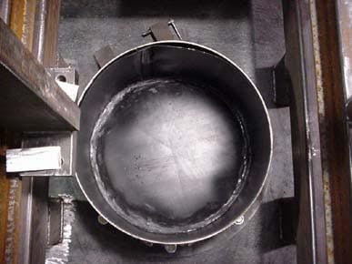
Figure 7. HDPE Cylindrical Liner Inserted in the Water Tank.
A cylindrical liner of 80 mil high density polyethylene (HDPE) was made to fit inside the steel cylinder (Figure 7). The liner had an open top, and the bottom was scored to create pie shaped sections so that when the bottom burst under pressure from the explosion it would open along the scored lines rather than being blown out in irregularly shaped pieces.
For experimental trials that required the use of flame detectors, three AFRL Fire Research Group photo-transistor detectors were used. Mounted at different locations around the test sample table, they all were aimed toward the center of the table where the pyrotechnic material was placed. The detectors were wired in parallel so that any single detector could initiate a response.
Two high speed cameras set to a frame speed of 3000 frames per second were used simultaneously to capture video of the experiments. The cameras were located on axes 90° apart so that views of the side and of the front of the test frame could be photographed. Videos from the cameras were used to determine when a detectable fire event began (onset of fire), response time of the BIDS, velocity and shape of the water spray, and duration from detectable event to fire extinguished. Use of two cameras not only gave two different views of the event, it also provided two data sets to compare for each experiment.
One, in some cases two, piezoelectric pressure transducers were used to measure incident pressure caused by the detonation of the BIDS explosive charge, or from rapid combustion of the pyrotechnic material. Set at a height above floor of 65 inches in accordance with MIL-STD-398, the sensors measured pressure at distances of 48 and 72 in from the center of the sample table. For some of the experiments a heat flux/temperature sensor was used, however it was determined afterward that the amplifier was not properly calibrated, and the recorded measurements were suspect.
Six experiments were conducted. Two were done primarily to determine the speed and shape of the water spray. One experiment was done to observe and record the automatic system response to a burn of 1 lb of MJU 32/38 magnesium-Teflon pyrotechnic flare material. One experiment was done to observe and record the automatic system response to a burn of 4 lbs of MJU 32/38 magnesium-Teflon pyrotechnic flare material, and one additional trial was done to record the unsuppressed characteristics of a burn of 4 lbs of the flare material for comparison. Finally, one experiment was done to determine the dynamic pressure distribution of the spray (dynamic pressure is a measure of the force exerted when the water impacts the table top).
The first two trials of the redesigned BIDS were done primarily to determine the water velocity and spray pattern of the system, and to measure incident pressure from the detonation. They also allowed comparison between the two different dilute explosive tiles and revealed the effect of recoil on the test frame. Flame detectors were not used in these initial experiments, and no combustible material was involved. Detonation of the BIDS charge was done remotely by a manual switch in a firing circuit. The high speed cameras and the data acquisition system used to record incident pressure were triggered from the same firing circuit.
For the first test of the automatic response of the BIDS to an actual fire, 1 lb of flare material was mounded in the center of the table directly beneath the 20 gal water tank. The distance from the tank to the table top was 36 inches. The flare material was ignited by an electric match, similar to an igniter for a solid propellant model hobby rocket, which received its signal through a manual switch in a firing circuit. The cameras and data acquisition system were triggered from the same circuit that initiated the signal to the electric match. The explosive tile with the higher density of explosive was used in the BIDS. The three phototransistor flame detectors were positioned at three different locations above the table 49 in, 52 in, and 55 in from the mound of flare material, and a single pressure gauge was positioned 48 in from the material. Signals from the detectors went to a Pyrotech International RAM/LAM (response acceleration module/low-cost acceleration module) controller. On receipt of a detection signal from the flame detectors the controller sent a triggering signal to a detonator that in turn initiated detonation of the explosive tile in the BIDS spray cone. The sequence of events was as follows:
- The electric match was ignited by a remotely initiated manual switch, which also triggered the high-speed cameras and data acquisition system.
- The flare material ignited.
- When the intensity of the burning material reached the threshold of detection, one or all flame detectors sent a signal to the controller.
- Upon receipt of a detection signal the controller sent a signal to initiate a detonator inserted into the explosive tile in the spray cone.
- The explosive tile detonated and caused a rapid rise in pressure under the spray cone.
- High pressure forced the bottom of the HDPE tank liner to open, and water was directed at the burning material.
- As the water under the cone was expelled, the remaining water in the tank on the outside of the cone was drawn through holes in the side of the cone and on to the burning material.
In the second test of the automatic response of the BIDS to an actual fire, 4 lbs of MJU 32/38 were used. This experiment was designed to reveal the effective suppression diameter of the BIDS and to determine whether the system could suppress larger amounts of pyrotechnic material. The equipment, procedures, and sequence of events were similar to those described above for the experiment with 1 lb of MJU 32/38. The flare material was arranged on the table top in four separate 1 lb piles located around the table at distances of 6 in, 12 in, 18 in, and 24 in from the center of the table. To create a worst case scenario, the four separate mounds were ignited simultaneously and independently by four electric matches. An explosive tile with the lower density of explosive was used. A second pressure detector was added at a distance of 72 in from the center of the table.
For comparison, a second experiment was done with the BIDS deactivated to record the characteristics of an unsuppressed burn.
The final trial was similar to the first two trials in that no combustible material was used, and the BIDS was initiated manually by a remote switch. The purpose of this trial was to measure the dynamic pressure distribution of the water spray. The explosive tile used was one with the higher explosive material density. PressurEx® pressure sensitive film was used to record pressure. The pressure range of the film was 70-350 psi. The film was cut and pieced into a 45 in square, then encased in a thin laminate to prevent the film from getting wet. The square of film was laid flat on the table top with one edge of the square directly below the center of the water tank such that only half of the spray pattern would be measured. Two pressure gauges positioned 48 in and 72 in from the center of the table were used to record incident pressure.
3. Results and Discussion
Water spray velocity was 500 fps for the explosive tiles with the higher density of explosive material and 420 fps for the lower density tiles. Water traveled the 36 in to the sample table top in 6 ms for the higher density tile and in 7 ms for the lower density tile. Maximum incident pressure caused by the higher density tiles was 0.7 psi at 48 in, and for the lower density explosive tiles the maximum incident pressure was 0.6 psi at 48 in. In the 36 inches of travel from the bottom of the spray cone to the table top the spray spread from an initial diameter of 20 in to a diameter of 66 in athe table top, and had a very uniform shape (Figure 8).
Operated in automatic with an actual burn of 1 lb of MJU 32/38 flare material, the system detected a flame and initiated response 1.3 ms after the first sign of flame. From the time that the pyrotechnic material started to burn, it took just 7.3 ms for the system to respond and put water on the burning material and just 16 ms to extinguish the fire (Sixteen ms is about the amount of time it takes a hummingbird to complete two strokes of its wings). Figure 9 shows captured high speed video frames from the experiment with 1 lb of flare material. The first frame shows the start of the fire, and this frame was used as the time-zero reference frame. The second frame shows water leaving the BIDS. The third frame shows water on the fire. The elapsed time between frames one and three was 7.33 ms.
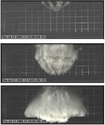
Figure 8. Captured High-Speed Video Frames Showing the Spray Shape. (Grid lines in the background are 6 in apart.)
Figure 10 shows incident pressure measured 48 in from the flare material for both unsuppressed and suppressed burns of 1 lb of material. Maximum incident pressure was reduced from 10.6 psi to 1.1 psi. For reference, onset of eardrum damage in humans occurs at about 5 psi.

Figure 9. Captured High-Speed Video Frames from Test Burn of 1 lb Mag-Teflon Flare Material at Times 0, +3.3, and +7.3 ms.
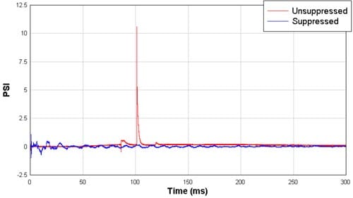
Figure 10. Incident Pressure Comparison at 48 in for 1 lb MJU 32/38 Flare Material.
In the case of the four 1 lb piles located at varying distances from the center of the table, the system detected a flame and initiated response 1.3 ms after the first sign of flame. It took just 5.9 ms for the system to respond and put water on the burning material, and the fire was extinguished in 42 ms. On average, it takes a human about 250 ms to blink his eyes. To put this in perspective, if you had been observing the experiment from a distance of 50 feet, the fire would have been detected and extinguished before you would have heard the bang from the BIDS firing (assuming dry air at 68°F, for which the speed of sound is 1.126 ft/ms), or you might have missed the event entirely if you happened to blink your eyes. Figure 11 shows captured high-speed video frames from both the unsuppressed and suppressed burns of 4 lbs of flare material. In both cases, the frames correspond to 0, 5.3, and 33 ms after ignition of the material.
In the unsuppressed burn, the pressure detector positioned 48 in from the center of the sample table was destroyed before any useful measurement could be made. In the suppressed burn, incident pressure at 48 in was 1.5 psi. The gauges at 72 in were unharmed in both experiments. Maximum incident pressure measured 72 in from the center of the sample table was 8.4 psi for the unsuppressed and 0.5 psi for the suppressed burn. Extrapolated to 48 in, the unsuppressed pressure would be about 25 psi. The maximum incident pressure allowed by MIL-STD-398 is 2.3 psi measured 65 in above the floor and at the closest point of approach expected for the head and face of someone working in the vicinity. Figure 12 is a graph showing the comparison of incident pressure time histories measured 72 in from the center of the table top for the unsuppressed and suppressed experiments with 4 lbs of MJU 32/38.
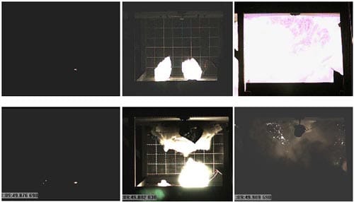
Figure 11. Unsuppressed (top) and Suppressed (bottom) Burns of 4 lbs of MJU 32/38 at Times 0, +5.3, and +33 ms.
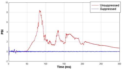
Figure 12. Incident Pressure Comparison at 72 in for Suppressed and Unsuppressed Burns of 4 lbs MJU 32/38 Flare Material.
The last experiment, using pressure sensitive paper, showed that the water spray reached a maximum dynamic pressure of about 300 psi. It also showed characteristics of the spray pattern not evident from high-speed video. Figure 13 is a color contour map of the pressure distribution. Pressure was measured only in one semi-circle because of the symmetry of the spray. Note from Figure 13 that the pressure distribution had a pattern that looked much like a spoked wheel with a radius of 21 in and eight spokes radiating from a central hub. The eight spokes correspond to the score lines that divided the bottom of the HDPE container into eight triangular shaped sections. When the bottom of the container opened, some of the triangular sections tore away from the sides of the container while other sections stayed attached and simply hinged outward. The triangular section at the far left in the figure does not have a distinct outer band of high pressure as do the other three sections, probably because it corresponded to a triangle that stayed attached while the other three sections tore away from the container. The velocity of the water spray as determined from high-speed video was 500 fps. Coupled with dynamic pressure measured on the pressure sensitive film, density of the spray can be calculated if t
he assumption is made that water velocity everywhere near the leading edge of the spray was the same. With that assumption, the areas where dynamic pressure was 300 psi had a corresponding water spray density of 11 lb/ft3, compared to a density of about 62.5 lb/ft3 for water at the same temperature. Areas where the dynamic pressure was 70 psi had a corresponding spray density of 2.6 lb/ft3.
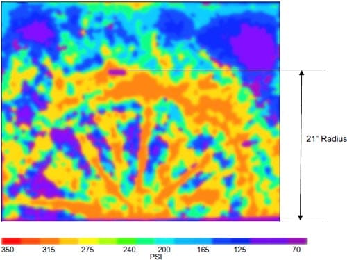
Figure 13. Color Contour Map of Pressure Distribution of One-Half of the BIDS Spray Pattern.
4. Conclusions
The BIDS ultra-high-speed fire suppression system is a promising start toward developing a system capable of protecting automated processes involving propellants and pyrotechnics. BIDS might also provide fire protection while processing high explosives. The second generation BIDS responded to fire from a highly energetic pyrotechnic material and suppressed the fire in 16 ms, comparable to the original BIDS but with greater volumes of initial and follow-on water and a wider and more dispersed spray pattern that were achieved without sacrificing velocity. The BIDS can suppress up to four pounds of pyrotechnic material spread over a four foot diameter while keeping incident pressure below the limits specified in MIL-STD-398. Reliable heat flux and temperature measurements have not yet been taken, but it is very likely that the redesigned BIDS performs at least as well as the original system at limiting heat flux and temperature to well below the limits specified in MIL-STD-398. The BIDS responds faster and puts water on the fire quicker than any existing ultra-high-speed suppression system in use. It is ideally suited to any application where propellants, pyrotechnics, or any other fast burning materials are processed.
The BIDS is limited to use in automated processes: processes done primarily by machine with little human intervention. This is a consequence of one of the most important characteristics of the BIDS, the speed at which water is propelled toward the fire. The difference in speed between the AFPDS and the BIDS is 250 fps and makes a difference of 12 ms getting water on a fire 36 in from the spray head. Figure 14 illustrates this point. The top frame is a picture of the flame size 5.9 ms after initiation of the flare material, the time when water from the BIDS would be just reaching the flame. The bottom frame is a picture of the flame 12 ms later, about the time that water from the AFPDS or other similar systems would reach the flame. The difference is dramatic, and it is likely that the fire could not be suppressed once it had progressed to the point captured in the picture on the right. The consequence is at 420 fps the force of the water per square inch is near 200 psi, enough to cause personal injury to anyone who might have an arm in the path of water discharged from the BIDS. Increasing the volume of water under the spray cone, or reducing the weight of the explosive charge, or a combination of both could be done to slow the water spray and subsequently lower the force of the spray, but doing so would defeat one of the distinct advantages of the BIDS. For this reason the BIDS would be appropriate only in automated processes and in situations where people would not be exposed to the direct path of the water spray. Still, that accounts for a large number of the steps in manufacturing, handling, storing, and processing of propellants, pyrotechnics, and other fast burning materials.
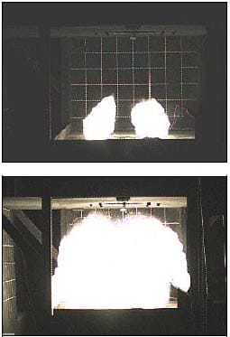
Figure 14 .Comparison of Flame Size 12 ms Apart
5. Recommendations
Research will continue at the DOD Fire Research labs at Tyndall AFB. We would like to find a better container than the current HDPE container being used, one that does not allow sections of the bottom to separate when the BIDS fires and throw pieces of HDPE in the vicinity of the fire, and one that does not contribute to forming areas of high density in the spray that result in excessive dynamic pressure. Experiments with larger amounts of pyrotechnic material in configurations like those found in manufacturing facilities need to be done to determine an upper limit to the system’s capabilities, and experiments need to be done for high explosives in layers thinner than their failure depths that burn rather than detonate and mimic conditions found in many automated processes at munitions facilities. More work is needed on the high speed flame detectors used with the BIDS. Experiments to determine their response to a variety of burning materials must be done, false alarm susceptibility must be determined, and if necessary, design changes must be made to enhance the performance of the detectors without sacrificing speed of detection. Finally, an industry partner must be found that can manufacture these systems for commercial sale.
REFERENCES
- Loyd, Robert A., Evaluation of Ultra_high-Speed Fire Protection Systems Presently in Service at Army Ammunition Plants, U.S. Army Armament, Munitions, and Chemical Command Safety Office, Department of Defense Explosives Safety Seminar, August 1994.
- NFPA 15: Standard for Water Spray Fixed Systems for Fire Protection, National Fire Codes, National Fire Protection Association, 2001 Edition.
- Carr, V., Cozart, K.S., and Wells, S.P., Advanced Fire Protection Deluge System Phase I Report, U.S. Army Defense Ammunition Logistics Activity, AFRL-ML-TY-TR-1998-4526, July 1998.
- MIL-STD-398, Shields, Operational for Ammunition Operations, Criteria for Design of and Tests for Acceptance, Department of Defense, November 1976.


