Matthew Francis Moran
Abstract
Normal knee function following total knee replacement (TKR) is determined by an appropriate balance of joint laxity and stability. TKR is increasingly being performed on patients 55 years of age and younger, and these patients are more likely to have postoperative complications than older patients. It has been speculated that younger patients place greater functional demand on their replaced joint sometimes exceeding the capabilities of the implants. The impetus behind this dissertation was the creation of novel methodologies, both computational and experimental, that could be used to systematically investigate the dynamic relationship between implant design and function. Four studies investigated the relationship between implant design or surgical technique and joint stability and function.
The first study involved the development of a dynamic computer simulation of a TKR implant range of constraint test. A rigid-body-spring model was utilized to compute implant contact forces and experimental measurements were used to validate the model. Model outputs compared favorably to experimental constraint values only when artifacts in the laxity testing simulator were represented.
The second study augmented the range of constraint test simulation by modeling the posterior cruciate ligament (PCL). The addition of the PCL made it possible to assess laxity in TKR designs that retain this ligament. A tight PCL can limit joint laxity and impair function following TKR. Two surgical treatment options, increased posterior tibial sloping and partial PCL release, were simulated to assess their individual and combined effectiveness at reducing PCL tension and improving laxity. Although both treatments were effective at increasing anterior laxity, only partial PCL release was effective at increasing overall anterior-posterior laxity.
The third study employed a novel dynamic mechanical TKR simulator to assess functional differences between two variations of a reduced patellar height. Reduced patellar height is likely to disrupt the extensor mechanism following TKR. The mechanical knee simulator applied physiological loads across both the tibiofemoral and patellofemoral joints. Both forms of reduced patellar height substantially increased the quadriceps force required to extend the knee. With a reduced patellar height, a symmetric patellar implant was more resistant to abnormal tracking than an anatomic patellar implant.
The final study investigated the micromotion of two cementless femoral components with different designs during squat, gait and chair rise simulations. The presence of micromotion above a certain threshold can prevent bony ingrowth and potentially lead to implant loosening. A novel method was developed to measure the pattern of micromotion between the femoral component and an underlying bone substitute. No statistical differences in micromotion were noted between the TKR designs for gait or chair rise simulations, but significant differences were found for squatting simulations. The micromotion of the femoral component was found to occur in three dimensions, contrary to previous reports.
In conclusion, this dissertation outlined novel methodologies used to investigate the role of TKR motion. Through these research methodologies new TKR designs can be evaluated and improved prior to implantation. Although TKR is an attractive and effective approach for thousands of patients afflicted with arthritis, future work should be directed at optimizing TKR design and surgical technique to further improve postoperative function.
LIST OF ACRONYMS
| AL | anterolateral bundle of the posterior cruciate ligament |
| AP | anterior-posterior |
| ASTM | American Society of Testing and Materials International |
| CAD | computer-assisted design |
| CR | cruciate retaining |
| CS | coordinate system |
| DOF | degrees of freedom |
| DVRT | differential variable reluctance transducer |
| FE | finite element |
| FEM | finite element model |
| IE | internal-external |
| LMC | least-material condition |
| MBK | mobile-bearing knee |
| ML | medial-lateral |
| OA | osteoarthritis |
| OP | osteoporosis |
| PCL | posterior cruciate ligament |
| PCR | posterior cruciate ligament retaining total knee replacement |
| PM | posteromedial bundle of the posterior cruciate ligament |
| PS | Posterior substituting total knee replacement design |
| QT | quadriceps tendon |
| RA | rheumatoid arthritis |
| ROM | range of motion |
| RSA | roentgen stereophotogrammetric analysis |
| SIMM | Software for Interactive Musculoskeletal Modeling |
| TKR | total knee replacement |
| UHMWPE | ultra high molecular weight polyethylene |
| VV | varus-valgus |
ACKNOWLEDGEMENTS
Throughout my entire doctoral work my wife, Megan, has provided consistent support and encouragement. Without her daily motivation and incredible positive outlook on life, I’m not sure I would have been able to complete this entire process and the following manuscript. Thank you so much all of your help Megan. My family has also been extremely supportive throughout my entire academic career, and I am forever grateful for all of the opportunities you have afforded me.
The following manuscript has reached this point due to the careful and meticulous editing of my advisor, Steve Piazza. When I began my graduate career five years ago, I never imagined how enjoyable it would be to work with Steve. Besides allowing me the freedom to find my own research path, Steve has supported and assisted me all along the way. Thanks Steve for making the last five years so much fun. I would also like to thank the entire Biomechanics Research Lab support staff. Thank you to Denny Rypka, Joe Strella, Tracy Wilson, Nick Giacobe and Nori Okita. Without your help and guidance this research project would not have been possible.
Finally I would like to thank all of the graduate students who I have had the pleasure of sharing an office space with for the past five years. It was been an incredible ride and something I am sure that I will miss. A huge thanks go to my
fellow Ph.D. students – Andy Fauth, Andy Hoskins, Greg Lewis, and Andrea Cereatti. Your advice and friendship was needed every step along the way and your input helped me to clear many obstacles.
CHAPTER 1
INTRODUCTION
Orthopedic biomechanics focuses on the study of mechanical and biological issues related to the human musculoskeletal system. With the progressive graying of the population of the United States due to the aging of the baby boomer generation, the incidence of orthopedic problems associated with increased wear and tear on the musculoskeletal system have increased substantially in recent years. Replacement of the articulating surfaces of the knee joint, total knee replacement (TKR), is performed over 300,000 times annually in the United States (National Institutes of Health Consensus Statement of TKR, 2003). In TKR, knee joint surfaces degraded as a result of osteoarthritis (OA), rheumatoid arthritis (RA), juvenile RA, osteonecrosis or other inflammatory arthritis are removed and replaced with metal (e.g., cobalt-chrome alloy) and plastic (polyethylene) implants. Typically the procedure is performed in patients aged 60-75 years, however both younger and older patients are now being afforded the option of TKR because of the recent evolution of implant design and surgical technique that has improved functionality and longevity.
The costs associated with joint replacement are also increasing. It has been estimated that 1.5 billion dollars was spent on 156,000 TKR procedures in 2000 alone (Maloney and Clohisy, 2003). With predictions that 18% of Americans will be over the age of 65 in 2025 (National Center for Health Statistics), it can be hypothesized that the amount spent on TKR procedures should rise substantially in the years to come. Over 20 companies in the United States design and distribute knee replacement components. The aging societal demographic coupled with a competitive free market should infuse the interest of optimizing TKR outcomes in the upcoming years.
Current orthopedic opinion on TKR is that it is a safe, cost-effective, and successful procedure for older patients exhibiting severe knee pain as a result of degenerative joint disease. Numerous long- and short-term studies report good to excellent clinical results in over 90% of TKR patients, and it is commonly referred to as one of the most successful surgeries in orthopedic history (Keating et al., 2002). However, caution should be taken when interpreting these results as significant gait abnormalities have been reported in TKR patients classified as having good clinical results (Benedetti et al., 2003). Dickstein et al. (1998) reported ⅓ of TKR patients were dissatisfied with their outcome despite being classified as having a good clinical outcome (Dickstein et al., 1998). A more recent study determined that only approximately 40% of functional impairment in TKR could be attributed to aging effects (Noble et al., 2005). These studies indicate that the standard protocols of assessing clinical outcome may not be the best predictors of post-operative functionality.
Based upon the exceedingly good outcome scores, it could be argued that the future of joint replacement surgery will not be focused on optimizing implant design or even improving surgical technique through computer-assisted navigation systems. Rather, future research attention will be diverted toward the regeneration of diseased articular cartilage through such techniques as tissue replacement, tissue-engineered implants or drug therapies. However, the ability of such techniques to reverse the arthritic process will not be realized for many years, and it is even debatable whether tissue engineering will ever provide a viable alternative for the treatment of a diseased joint (Scapinelli et al., 2002).
Although outcome studies suggest that TKR is an effective procedure, their results indicate that further improvements to TKR are possible. The following statement from the 2003 National Institutes of Health Consensus Statement on TKR best delineates the current indications for further study within this field:
Despite the increased success of TKR, questions remain concerning which materials and implant designs are most effective for specific patient populations and which surgical approach is optimal for a successful outcome.
Since TKR has become more common within younger patients (< 55 years), younger age has been cited as the second leading factor contributing to revision within 2 years following surgery (Heck et al., 1998). It is speculated that the more active lifestyle of these younger patients places a greater physical demand on their replaced joint. This increased demand contributes to prosthetic failure and raises questions about the relationship between implant design, altered knee kinematics, and complications (Laskin, 2002).
This dissertation outlines the development of two novel computer models and an experimental mechanical knee model used to investigate two functionally-relevant TKR issues. The computer models simulated a standard bench-top experiment used to study knee implant design and functionality. With recent computing advancements, the speed of computer simulation has substantially improved and the use of these models as potential “tools” within the implant design cycle has been realized. Numerous simulations were run to address simultaneously the influence of implant design and surgical variables on joint functionality. The models represent improvements over standard experiments in their elimination of certain methodological limitations and the speed with which results may be obtained.
1.1 Unifying Theme
The goal of any knee replacement procedure is to alleviate pain and restore functionality to the patient. This knee must be stable yet allow varied movements associated with activities of daily living. Climbing up stairs or rising from a chair are increasingly difficult activities when the knee is not functioning properly. The impetus behind this dissertation was the creation of novel methodologies, both computational and experimental, that could systematically investigate this dynamic interplay between joint stability and function. All four studies investigated the relationship between either implant design and/or surgical technique with the replaced joint stability and function.
The first computer model that was developed simulated both anterior-posterior and rotational motions of knee implants within a standard testing frame. The American Society of Testing and Materials International (West Conshohocken, PA) recommended certain testing methods for knee implants with the “intent of developing guidelines for the assignment of constraint criteria”. Artifacts present within the testing apparatus were identified and removed from the simulation to allow the unbiased comparison between implants. Subsequent simulations were run to examine the sensitivity of joint constraint measurements to different experimental options. Recommendations were then given to improve the present testing protocol and inform the design of new testing frames.
The second study enhanced the previous model with the addition of the posterior cruciate ligament (PCL). This addition allowed an improved comparison of implant designs that retain this ligament versus those that substitute for it. Both partial ligamentous release and increasing the posterior slope of the tibial insert have been cited as treatment options if the PCL is excessively tight during TKR. Specifically, the effect of partial PCL release was investigated with four different degrees of posterior tibial sloping and with two tibial insert designs. Simulation results were compared to in vitro studies for verification and fundamental differences between the treatments were identified.
The third study developed and used a dynamic mechanical knee simulator to investigate the effect of pat
ellar height on quadriceps efficiency. The mechanical knee was actuated to simulate a deep squat utilizing a standard knee extension testing rig (Cain, 2002). This rig actively extends the knee and resists applied flexion through actuation of a simulated quadriceps tendon. Patellar height can be reduced through either patellar ligament scarring or joint line elevation following implantation (Grelsamer, 2002). Both of these situations were simulated within the mechanical knee model and their subsequent effect on knee extension efficiency was determined. Simultaneously, the roles of two commonly-used patellar implants were also investigated in this study. A method for near real-time computationally-assisted visualization of TKR implants during the testing procedure was developed that has potential applications during cadaveric experimentation.
The fourth study in this dissertation altered the previous mechanical model to simulate a PCL-retaining femoral component implanted in osteoporotic bone. Two methods of fixing the femoral component to the underlying bone exist currently: cemented and cementless. Cementless fixation techniques rely on the underlying bone to dynamically invade the porous lining of the implant and create a rigid bond. This bone ingrowth is compromised by the presence of relative motion between the component and the surrounding bone. It has been reported that this motion, termed micromotion, can undermine rigid fixation if magnitudes exceed 150 µm (Pilliar et al., 1986). The effect of femoral component design on the potential for micromotion has received minimal research attention. The mechanical knee model was adapted and gait, squatting, and chair rise simulations were performed on two femoral component designs that differed in their required bony cuts. A novel method of assessing rigid body motion using three position sensors was developed and micromotion patterns were compared between designs.
All models, either computational or experimental, developed within this dissertation represent improvements of standard bench-top experimental protocols presently used today. By augmenting these models, research questions regarding the stability and function of implant design can be assessed in a timely fashion during the design cycle. Although each model addressed a separate issue regarding stability and functionality, the models are similar in that they are based upon extensions of bench-top experiments used to evaluate and evolve implant designs and surgical technique.
1.2 Clinical Significance
All four studies comprising this dissertation have either indirect or direct clinical significance. Noble et al. (2005) postulated that future improvements within TKR would require detailed attention to the “design and placement of the prosthetic components, the treatment and preservation of soft tissue structures”. The first study within this work was focused on the improvement of an experimental protocol used to assess implant design and its relation to joint laxity. A functional knee joint requires the correct combination of laxity and stability to allow and support a range of movement possibilities. Implant design is likely to alter the passive knee constraint characteristics and potentially affects the success of a replaced knee joint. The second study examined two treatment options for the presence of a tight PCL, a soft tissue structure, and elicited potential fundamental differences in their effect on joint function. The third study examined both the design of the patellar component and the functional effect of two possibilities of reduced patellar height following TKR.
The fourth study examined the role of two femoral component designs and cementless implant fixation. The controversy regarding implant fixation can be summed up in the following statement:
The 1980s saw a surge of such uncemented (cementless) implants, some of which had good results whereas others were disastrous. Surgeons then again began questioning whether to return to the acrylic cement they had used in their youth. The pendulum has still not settled on either the cemented or the uncemented side. – Laskin (2001)
Fixation problems accounted for over 24% of revisions in a recent series of 221 TKR revisions (Sharkey et al., 2002). Although the present study will not settle the debate described by Laskin, it did attempt to relate implant design and fixation. A better understanding of this relationship could eliminate cementless femoral component loosening problems and perhaps swing the “pendulum” to one side or the other.
1.3 Overview
This thesis is organized to provide the reader with substantial background information in Chapter 2 before discussing the four distinct studies in Chapters 3-6. The Chapter 2 provides a cursory overview of total knee replacement procedure and implant design considerations. A thorough overview of the literature is provided on the spectrum of bench-top experimental designs utilized to investigate TKR motion. Finally, past computer models of TKR motion are presented and references are given to more complete reviews of anatomical knee models. Chapters 3-6 are presented as separate projects with pertinent background, methodology, results and discussion. Chapter 3 details the simulation of the standard “range of constraint” test to study the effect of secondary degrees of freedom on both anterior-posterior and rotational laxity. Chapter 4 augmented this model with the posterior cruciate ligament and assessed the effect of two surgical techniques commonly performed during TKR procedures. Chapter 5 describes the development of a novel mechanical TKR model that was used to investigate the mechanical differences between two mechanisms of patellar height alteration. Chapter 6 improved this mechanical knee model to assess the effect of femoral component design on implant fixation. Finally, Chapter 7 attempts to unite the four separate projects and draw conclusions on the dynamics between implant design and knee function. Particular attention is given to relating the results of these models to the clinical problems addressed in the 2003 National Institutes of Health Consensus Statement on TKR. Appendix A thoroughly details the implementation of the Iterative Closest Point algorithm (Besl and McKay, 1992) in MATLAB for the accurate registration of manufacturer-supplied computer assisted design drawings. Appendix B outlines modifications that were made to the existing knee simulator. Appendix C provides detailed description of the mechanical knee model utilized in the studies of Chapter 5 and 6. Appendix D describes the method developed to computationally determine implant contact from kinematic data. Appendix E provides full documentation of the experimental protocol used in Chapter 6.
CHAPTER 2 – LITERATURE REVIEW
2.1 Total Knee Replacement
Although total knee replacement (TKR) originated with the hinged prosthesis over 100 years ago, the modern era of TKR began as a result of the combined work of a number of engineers and surgeons who developed the condylar-style implant between the years of 1969 and 1980 (Ranawat, 2002). Today the procedure is seen as a safe and effective treatment for endstage osteoarthritis. A meta-analysis of 130 TKR outcome studies reported good to excellent results in 89.3% of patients (Callahan et al., 1994). Current biomechanical research is driven toward understanding knee function and pathomechanics to further reduce complications and improve functionality following TKR (Green, 2001).
The standard tricompartmental TKR procedure involves the removal of diseased articular cartilage from the tibia, femur and the patella, although the orthopedic community remains divided on whether the patella should be resurfaced. Subchondral bone beneath the surface of the diseased cartilage is cut using a bone saw and anatomically-aligned jigs that create surfaces that fit the im
plant’s design. The femoral bone-cartilage complex is replaced with a metal replacement (usually a cobalt-chrome alloy) that is size matched and either cemented or press-fit to the remaining bone. The tibial bone-cartilage complex is replaced with a metal tray and stem that is inserted and cemented within the intramedullary canal of the tibia. Finally, an ultra high molecular weight polyethylene (UHMWPE) tibial insert is snapped into the metal tray and serves as the replacement for the tibial plateau. More recent mobile bearing designs have allowed rotation or sliding of the insert relative to the tray (Section 2.1.1). Either an asymmetric (anatomical) or symmetric (dome) shaped polyethylene implant is used to replace the posterior surface of the patella (Figure 2-1).,/
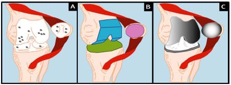
Figure 2-1: TKR Procedure: Degenerative joint disease leads to the destruction of articular
cartilage on femur, tibia, and/or patella (A). Diseased articular cartilage is removed using a
bone saw and anatomical jigs (B). Metal femoral component, metal tray and polyethylene
insert (tibial component), and polyethylene patellar button are
cemented or press-fit to subchondral bone (C).
Although TKR is an extremely successful surgery, more than 22,000 cases (3-7%) are required to be revised annually (Heck et al., 1998; Sharkey et al., 2002). In a retrospective series of 212 total knee cases that required revision, the causes for revision were as follows:
polyethylene wear (25%)
loosening (24%)
instability (21%)
infection (18%)
arthrofibrosis (15%)
malalignment (12%)
extensor mechanism deficiency (7%)
avascular necrosis patella (4%)
periprosthetic fracture (3%)
isolated patellar resurfacing (1%) – (Sharkey et al., 2002) (Figure 2-2)
These summed percentage exceeded 100% because more than one etiology was present in many revision cases. These etiologies are consistent with those reported by Rand and Bryan (1982) in a study of 142 failed TKRs, but if revision takes place within the first five years postimplantation, then infection and instability are the primary causes (Fehring et al., 2001). The percentages listed may be skewed because of the close relationship between factors. For instance, malalignment and extensor mechanism deficiency are likely to contribute to abnormal kinematics and subsequently to excessive polyethylene wear. Excessive polyethylene wear becomes a “catch all” for other factors and may mask the underlying etiology. In fact, in many cases the true etiology of revision TKR is multifactorial. Regardless of the failure mechanism the following three recommendations are consistently cited to reduce the number of failures: (1) improved design, (2) better materials, and (3) more accurate surgical technique.
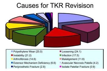
Figure 2-2: Adapted from Sharkey et al. (2002). Pie graph depicting the causes
of TKR revision in a study of 212 total knees requiring revision within the first 3 years
post-implantation. Percentages are given in ( ). The summed percentage exceeded 100% because
more than one cause was seen in many revised knees.
2.1.1 Design Considerations
The goal of any total knee design is to restore “normal” knee kinematics, however this notion of “normal” may not be (1) consistent between patients or (2) even present in a patient pre-operatively. Functionality of the surrounding soft tissues and musculature influence motion following TKR (Walker and Sathasivam, 2000). Replicating normal motion is necessary to create pre-operative ligament strains that contribute to knee laxity and stability. During knee flexion the tibiofemoral contact point translates posteriorly, thus increasing the moment arm of the quadriceps muscle group and effectively improving knee extensor efficiency. This translation has been termed “femoral rollback”. Greater flexion is also achieved through rollback as posterior soft tissues are able to clear the femur. Since the radius of the femoral medial condyle is approximately ½ that of the lateral condyle, a concomitant “screw-home” external rotation occurs in the tibia as the knee is extended (Andriacchi, 2000).
Despite the fact that patellofemoral complications are commonly cited as a major reason for TKR revision, a universal notion of “normal” patellar tracking does not exist (Grelsamer and Weinstein, 2001). One of the problems associated with measuring patellar kinematics is the difficulty in assigning local joint coordinate systems. The absence of identifiable bony landmarks and the number of methods employed make comparisons between studies difficult (Katchburian et al., 2003). Despite discrepancies between studies, Katchburian et al. (2003) noted in their review of patellar tracking studies that some common “agreements” do exist between studies. In general the patella translates medially in early flexion followed by a lateral displacement at higher levels of flexion, however, results for patellar tilt and rotation are variable. Near full extension, when the patella is not in contact with the trochlear groove, soft tissues guide its motion, but after patellofemoral contact is initiated it is the patellofemoral contact force that guides patellar tracking (Heegaard et al., 1995).
The success of modern TKR has steadily improved since its inception over 30 years ago (Green, 2001). This improvement has occurred because of knowledge garnered from clinical experience, experimental testing and computational studies on implant design (Ewald and Walker, 1988). Implant geometry influences knee kinematics, stability, range of motion, contact stress, polyethylene wear, and ultimate prosthesis longevity (Wright, 2000). Despite consistently good outcomes following TKR, there remain disagreements in the orthopedic community regarding design philosophy. Presently, four types of TKR designs are used by orthopedic surgeons: (1) posterior cruciate ligament retaining (PCL-retaining), (2) posterior cruciate ligament sacrificing (PCL-substituting), (3) mobile-bearing knees (MBK), and (4) guided motion knees (Walker and Sathasivam, 2000). Although each design type has purported advantages over their counterparts, no consensus has been reached regarding which implant provides the most consistent and best results. This brief review will only discuss the main design features of the four knee components as a full comparison involving wear issues and laxity measures is beyond the scope of this thesis and has been presented elsewhere (Walker and Sathasivam, 2000).
The greatest advantage of the PCL-retaining design is the retention of a natural intracapsular ligament. Vince (1996) termed this approach “biologic” because the PCL may allow the replaced joint to retain normal knee function. Retention of the PCL provides: (1) constraint of anterior femoral subluxation, (2) femoral rollback, (3) secondary constraint to varus/valgus laxity and (4) increased propioception of the knee (Munjal and Krackow, 2001). The primary ro
le of the PCL is the constraint of anterior translation of the femur relative to the tibia. With the retention of the PCL, constraint of femoral anterior translation is provided via a soft tissue as opposed to components that must provide this constraint through design features. Anatomically, the PCL is lax in extension and tightens as the knee flexes, thus causing a posterior translation of the femur relative to the tibia (Figure 2-3). Mechanically, a posterior translation of the tibiofemoral contact point would effectively increase the moment arm of the quadriceps group and better optimize knee function. The major drawback to PCL-retaining designs is the requirement for accurate femoral and tibial bony cuts to properly tension the PCL both in extension and flexion (Haas and Saleh, 2001).
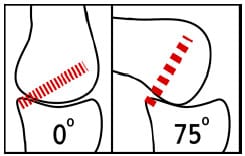
Figure 2-3: Schematic demonstrating the functional behavior of the posterior cruciate
ligament. In extension the fibers are predominantly lax, but as the knee flexes
the fibers become stretched. This tension is thought to cause the posterior translation of
the femur known as “rollback”.
Despite the purported advantageous of retaining the PCL, a number of surgeons routinely sacrifice the ligament. A recent survey revealed that 50.4% of surgeons routinely sacrificed the PCL while 49.6% routinely retained the ligament (National Center for Health Statistics, 1999). Because of the loss of the PCL functionality these designs must constrain anterior femoral subluxation and induce femoral rollback. These needs are met by an intercondylar cam-spine mechanism and posterior displacement of the trough of the dished tibial insert (Figure 2-4) (Walker and Sathasivam, 2000). The design features help to control rollback and attain gait kinematics similar to PCL-retaining designs (Wilson et al., 1996). With the resection of both cruciate ligaments and the elimination of PCL tensioning, this design is technically less demanding to implant than PCL-retaining designs (Haas and Saleh, 2001).
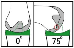
Figure 2-4: Schematic demonstrating the cam-spine function of PCL-substituting
designs. At full extension the cam-spine provide anterior constraint of femoral component.
As the knee flexes cam-spine interaction (red circle) help to drive the femur posterior
and induce femoral “rollback”.
The native knee has menisci, horseshoe-shaped fibrocartilage extensions of the articulating cartilage atop the tibial plateau. Functionally the menisci provide shock absorption, load distribution, joint lubrication, and stability to the knee (Fithian et al., 1990). The ability of the menisci to migrate in the anteroposterior (AP) direction increases functional knee laxity, especially on the lateral condyle where AP displacements are greater than the medial. TKR designs that attempt to incorporate meniscal function are called mobile-bearing knees (MBK). Additional degrees of freedom are introduced into the design by allowing the movement of the tibial insert relative to the tray in which it is housed. There are a number of different schemes in which these DOFs can be implemented within the design and each can affect performance (Walker and Sathasivam, 2000). Theoretically, a MBK design can better mimic AP motions of the natural knee and provide larger contact areas throughout the range of motion. In a review of MBK clinical results, Callaghan (2001) concluded that the survivorship of these knees is comparable to fixed-bearing knees if they are implanted with the same level of precision. In contrast, a clinical review of the Accord Johnson-Elloy MBK (Thackeray; UK) reported good 5- 8 year results, but significantly poorer long-term results as compared to studies reporting on fixed-bearing TKR (Norton et al., 2002). The poor results were due to massive osteolysis, destruction of bony tissue, and the study brings into question the long-term performance of other MBK designs. The main MBK complications include (1) dislocation of mobile bearings, (2) osteolysis secondary to implant wear, and (3) implant fracture. A recent biomechanical study of the stair-climbing of patients with MBK and fixed-bearing TKR revealed a decreased knee extensor moment in MBK patients, indicating a potential deficiency within the extensor mechanism (Catani et al., 2003). Although the proposed benefits of the MBK design are conceptually intriguing, further clinical and experimental studies are needed to substantiate these claims.
Guided motion knees, a fourth type of TKR design, attempt to further imitate native knee motions through more sophisticated bearing surface design. These design changes can be utilized either with or without the retention of the PCL. An example of a guided motion knee is the Wright Medical Medial Pivot knee (Wright Medical Technology; Arlington, TN) in which the medial condyle of the tibial insert is more dished (better congruency) than the lateral condyle. This asymmetry creates internal-external pivoting of the femur about the medial condyle. Fluoroscopic gait analysis of patients with this medial pivot knee and patients with a normal PCL-retaining design demonstrated that a “medial pivot motion” was present in patients with the medial pivot knee (Schmidt et al., 2003). Future clinical studies need to be performed to assess if functional performance is actually improved in patients using guided motion knees. Although the clinical value of such design types has yet to be substantiated, they do highlight the dynamic relationship between design and function and the potential for further improvement in the design of TKR implants.
Two types of the patellar implant designs are predominantly used in clinical practice today – anatomical and symmetric. Both implants are made from UHMWPE and are attached directly to the exposed subchondral bone. There are two methods of fixation of the implant onto the residual patellar bone: inset and onlay (Lachiewicz, 2004). The inset method recesses a circular dome with a single fixation peg while the onlay method usually cements the implant on the cut surface. Lachiewicz (2004) states that neither method has proven to be superior as far as implant fixation. Since the patella is subjected to contact forces 1-1.5 times body weight during gait and up to 3.3 times body weight in activities such as stair climbing (Reilly and Martens, 1972), the importance of congruity between the retropatellar surface and the femoral trochlear groove is critical with regard to polyethylene wear. Nearly every femoral component design presently in use today includes an anterior flange to improve tracking near full extension as a solution to reports of subluxation in the resurfaced patella (Vince and McPherson, 1992).
The native patella has an asymmetric distribution between its medial and lateral facets with the median crest approximately 5.5 mm medial to the patella midpoint (Dalury and Dennis, 2003) (Figure 2-5). One design philosophy attempts to recreate this asymmetric distribution and is generally termed “anatomic”, while its counterpart is termed “symmetric” because of equal facet distribution. Functionality and wear of the patellar implant will be determined by its interaction with the
femoral component groove, which can similarly have an anatomic or symmetric design. Hsu and Walker (1989) found that an asymmetric patellar implant wore less in an anatomically designed groove, while a symmetric dome design wore less in a symmetrically designed groove. Malo and Vince (2003) stated that an anatomic design has a greater capacity to track poorly when it is positioned poorly, thus indicating that a symmetric implant may be more forgiving to surgical error.

Figure 2-5: Superior schematic view of patella (A), symmetric dome implant (B),
and anatomical or asymmetric implant (C). Median crest of patella is 5.5 mm medial to red midline.
The amount of residual bone after cutting is typically between 10-15mm.
2.2 Overview of Experimental TKR Studies
Several experimental methodologies have been developed in the study of TKR motion and function. These methodologies have utilized a varied approach to investigate such things as UHMWPE wear, implant constraint, implant loosening, surgical technique, surgical error, load transmission, and joint kinematics across both the tibiofemoral and patellofemoral joint. Although experimental studies are once removed from in vivo clinical studies, they offer distinct advantages regarding control of independent variables. For example, measuring quadriceps force as a function of knee angle would be extremely difficult in vivo, but in a cadaver knee model this quantity is easily quantified. Experimental bench top studies may be classified into the following two categories: knee joint laxity testing and dynamic functional testing (Figure 2-6). Dynamic functional testing can be further sub-classified into mechanical and cadaver models. Although sheep and canine models have been used in the assessment of the TKR implant fixation (e.g., Bellemans, 1999), these studies are beyond the scope of the present review.
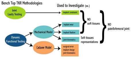
Figure 2-6: Schematic demonstrating two main bench top research methodologies used
to investigate issues related to TKR motion.
2.2.1 Joint Laxity Testing
Isolated bench-top simulators have been developed in the study of joint laxity (Chapter 3). These simulators measure the resistance to motion that a TKR design provides but do not model the surrounding soft tissue. In order for proper joint functioning, a certain level of laxity must be present through the flexion arc to accommodate a spectrum of movement possibilities (Blankevoort et al., 1988). Passive constraint following TKR is the product of both congruity of bearing surfaces and soft tissues crossing the joint space (e.g., joint capsule). Specifically, tibial insert curvature will have a direct effect on passive constraint. Designs with a high degree of conformity (dished tibial inserts) experience increased contact areas and reduced contact stresses (Collier et al., 1991; Blunn et al., 1997) but these designs may restrict laxity. On the other hand, a flat tibial insert provides minimal resistance to either AP displacement, varus-valgus angulations, or internal-external rotations but contact stresses could be elevated thus increasing the chances of UHMWPE wear. As a result of these conflicting requirements, an objective means of assessing implant constraint was developed to design implants for a spectrum of laxity needs.
Numerous investigators have reported the laxity properties of TKR implants in isolation (without soft tissues) using a bench-top simulator (Werner et al., 1978; Thatcher et al., 1987; Klein et al., 2003; Haider and Walker, 2005). The experimental design of these setups were similar in that the tibial and femoral components were rigidly fixed to a testing frame that had the ability to apply specific forces/moments or displacement/rotations (Figure 2-7). A compressive axial force was applied through the joint and either AP displacement and/or internal-external (IE) rotation prescribed. The force or torque required to move the implants was recorded. Force-displacement and/or torque-rotation curve were used to describe joint constraint at various instances throughout the motion for multiple flexion angles. Although these bench-top laxity simulators did not include soft tissues, the repeatability of testing conditions presented an opportunity to objectively compare implant designs. A standard protocol has recently been proposed for this purpose by the American Society of Testing and Materials (ASTM; ASTM Designation F 1223; Standard Test Method for Determination of Total Knee Replacement Constraint). Walker and Haider (2003) have argued that this type of laxity testing could create an objective means of comparing implants and also the ability to “explore the behavior of a TKR at its extremes of motion”.
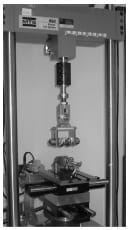
Figure 2-7: Photograph depicting a typical bench-top knee simulator in the assessment
of TKR passive constraint (Stryker Orthopaedics; Mahwah, NJ).
2.2.2 Dynamic Functional Testing
Dynamic functional knee simulators of TKR motion have been developed and utilized extensively in the study of (1) UHMWPE surface wear, (2) joint kinematics and kinetics, and (3) implant fixation. Dynamic knee simulators attempt to recreate the kinematics and kinetics of functionally dynamic knee activities (e.g., gait, squatting). Both mechanical and cadaver models have been used depending on the nature of the study. Most mechanical knee simulators are isolated without any attempt to recreate the surrounding soft tissues, however more sophisticated models have included the effective restraint of soft tissues (Walker et al., 1997; DesJardins et al., 2000). Although a mechanical knee model creates a greater control of input variables, this advantage comes at the cost of a less physiological model. As a result cadaver knee models have been utilized extensively within the literature to study TKR motion (Jiang et al., 1993; Mahoney et al., 1994; Petersilge et al., 1994; Matsuda et al., 1997; Arima et al., 1998; Singerman et al., 1999; Wulff and Incavo, 2000; Matsuda et al., 2000; D’Lima et al., 2000; Tanzer et al., 2001; Li et al., 2001; D’Lima et al., 2001; Weale et al., 2002; Whiteside and Nakamura, 2003; Sultan et al., 2003; Most et al., 2003).
Numerous researchers have investigated tibial insert wear through the use of a dynamic knee simulator (McEwen et al., 2005). Tibial insert wear may limit longevity of TKR components through the generation of microparticles of UHMWPE in the joint space. It has been shown that these particles may increase the risk of infection (Howling et al., 2001) and ultimately lead to osteolysis (Ingham and Fisher, 2000). Wear simulators apply either physiological tibiofemoral knee displacements/rotations or forces/moments based upon reports presented in literature (Walker et al., 1997). In order to measure volumetric plastic wear millions of cycles are performed and pre- and post- gravimetric measurements are taken (McEwen et al., 2005). Up to 30 million cycles have been suggested to simulate 10-20 years of actual wear (Seedhom and Wallbridge, 1985). Although this process may take months to complete, it is a required step for new designs pr
ior to clinical use (Walker et al., 1997).
Dynamic mechanical knee simulators attempt to mimic natural knee motions through the application of either (1) rotations/displacements or (2) forces/moments (Walker et al., 1997). Walker et al. (1997) demonstrated that knee simulators that applied input forces/moments directly to the femur or tibia without muscle action simulation produced the most realistic wear patterns. Other simulators, such as the New Jersey simulator and the Leeds simulator (Dowson et al., 1985), have been proposed with slight variations to joint constraints and initial configurations. Despite the differences between simulators, the overall goal of attaining normal knee motion without the presence of surrounding soft tissues was a common feature.
Although the importance of soft tissues in providing passive restraint to native knee laxity is widely accepted, relatively few dynamic knee simulators have incorporated these tissues. A more sophisticated force controlled knee simulator, the Stanmore/KC Instron, has recognized the weakness of the aforementioned simulators and incorporated soft tissue characteristics to simulate gait (Walker et al., 1997; DesJardins et al., 2000). Soft tissue restraints of both AP displacement and IE rotation were modeled within the simulator as a coupled linear elastic spring system. DesJardins et al. (1997), utilizing this improved knee simulator, reported implant reaction forces, soft tissue restraint forces and tibial motion patterns for eight TKR designs during a simulated gait cycle. The authors were able to determine which TKR designs relied on soft tissues for restraint as opposed to implant congruity. Incorporation of soft tissue improves the correlation to physiologic knee patterns and provides greater insight into function. Although this knee simulator has improved upon the aforementioned simulators, it still lacks a patellofemoral articulation which may substantially change the loading environment of the joint.
The standard dynamic knee simulators that have been used for testing the motion of cadaver knees implanted with TKR implants are typically derivatives of the original Oxford Rig (Zavatsky, 1997). A more detailed review of dynamic knee simulators has been provided elsewhere (Cain, 2002). These simulators provide viable simulations of rising from a chair, squatting and even gait. An axial load applied at the hip causes an obligatory flexion moment at the knee which is counteracted by an actuated quadriceps tendon. Hamstring actuation via a pulley and hanging weight has been added to study the effect of cocontraction during knee extension (MacWilliams et al., 1999). The knee rig allows flexion-extension patterns to be repeatedly performed within the cadaver knee. Testing can occur pre- and post-implantation to compare TKR motion to native knee motions. Cadaver TKR models have been used to study numerous topics including patellofemoral forces, effect of patellar resurfacing, implant position, strain levels within the posterior cruciate ligament, etc.
Although cadaver models offer considerable advantages over the aforementioned mechanical knee models, there remain limitations to this design model. Typically the quadriceps is loaded with one straight line of action approximating the vastus intermedius, although the quadriceps is composed of four distinct muscle groups. If the quadriceps is represented by more muscle groups, then the exact ratio of physiological muscle forces can only be approximated at best (Walker and Haider, 2003). Furthermore, the hip joint is constrained to translate only vertically and most designs do not include an offset for the femoral neck. Despite these limitations cadaver knees tested within functional dynamic knee simulators have often been used to study TKR motion.
2.3 Application of Computer Simulation in the Study of TKR
The goal of a biomechanical computational model is to represent a complex system, the human musculoskeletal system, in a simplified manner. In so doing, it becomes easier to identify the main constituents of the system and how those constituents influence overall function. As a result of this simplification there is the risk that key components are either overlooked or improper characteristics are assigned to modeled structures to account for structures not represented. Model outputs should always be viewed cautiously as they could be matching experimental output in an erroneous way. Two of the major limitations of utilizing a computer modeling approach involve validation and parameter determination. However, combined with experimental data, an analytical approach can give further insight into a biological system. Despite the inherent difficulties associated with modeling, it does offer the following significant advantages over both clinical and experimental studies: (1) a safe environment to conduct experiments, (2) precise control of independent variables, and (3) time efficiency. The true value of numerical modeling of biological systems was succinctly summarized by Oreskes et al. (1994) with the following statement:
Models can corroborate a hypothesis by offering evidence to strengthen what may be already partly established….Models can be also used for sensitivity analysis – for exploring “what if” questions…Thus, the primary value of models is heuristic: Models are representations, useful for guiding further study but not susceptible to proof.
Computational modeling studies of TKR motion have contributed to advancements in both surgical technique and implant design over the past 20 years. Mathematical TKR models can be classified as (1) finite element analysis, (2) kinematic simulation, or (3) dynamic simulation. The particular research question at hand should dictate which modeling approach to use, since each approach contains unique advantages and disadvantages. The present review is limited to TKR computational modeling studies and does not include models of the native knee. Although such studies have improved our understanding of knee function, it is beyond the scope of this review and has been presented elsewhere (Hefzy, 1988; Heftzy and Cooke, 1996; Piazza and Delp, 2001).
Finite element (FE) analysis has been used to improve TKR designs through the determination of contact stresses within the tibial and patellar polyethylene implants (Paganelli et al., 1988; Heegaard et al., 2001; D’Lima et al., 2003). Determination of the stresses within implants has direct implications for implant wear and longevity. Although recent advances in computing power have decreased the time required for FE analysis, incorporating this analysis within a dynamic simulation is difficult. As such, a more thorough examination of computationally less intensive TKR models is given now.
2.3.1 Kinematic Models
Rigid body kinematic models are concerned with determining the motion of total knee components from their geometry, without regard for external forces and moments. Although these models require substantial assumptions, they have been used in the study of TKR to study how joint function is influenced by surgical variation and implant design. The central assumption of such models is that implant geometries dictate motion. Although it is generally accepted that soft tissue contribution to TKR motion is substantial, these models still have potential uses in the improvement of knee design and surgical technique.
Walker (1985) developed a 2D sagittal model of the total condylar III, a PCL-substituting design. By applying cadaveric knee motions to the 2D model, Walker was able to optimize dimensions of the tibial spine and femoral cam in order to improve the following five criteria for implant evaluation: (1) restraint of posterior subluxation, (2) height of cam-spine contact, (3) residual bone stock in intracondylar notch, (4) patellar impingement on spine, and (5) posterior height of femoral component. Low et al. (2000) used a similar
approach in the Dynamic Analysis and Design software (DADS) to optimize the design of a high flexion knee intended for an Asian population. Specifically, the design was checked for posterior impingement at large flexion angles. Although these studies used simple models containing many assumptions, they represent the potential of mathematical modeling to optimize design based upon clinically observed criteria.
Garg and Walker (1990) created a more sophisticated 3D model of a PCL-retaining TKR design and simulated motion by applying an Eulerian transformation on the femoral component based upon the cadaver work of Kurosawa et al. (1985). The authors concluded that anterior displacement of the femoral component and posterior sloping of the tibial component increased range of motion in PCL-retaining TKR. Similarly, Piazza et al. (1998) investigated posterior sloping in the tibial compartment of a PCL-sacrificing design using a 2D sagittal plane model in which motion was generated by imposing implant contact criteria. This analytical study found that posterior sloping of the tibial insert may not be beneficial when the PCL is sacrificed because initial cam-spine contact occurs at a greater flexion angle thus limiting rollback. These studies highlight two different methods of simulating motion within kinematic models.
Anterior-posterior stability has also been studied in PCL-sacrificing designs via kinematic modeling. Both Kocmond et al. (1995) and Delp et al. (1995) studied the interaction between the cam-spine mechanism used to substitute for the loss of PCL functionality. It was found that changes in design features to maximize flexion increase the chance for tibiofemoral dislocation. It was determined that as the knee flexes the distance from the top of the spine to the bottom of the femoral cam, termed “dislocation safety factor”, becomes smaller. This reduction increases the chance for posterior dislocation depending on the height of the spine.
2.3.2 Dynamic Models
Dynamic TKR models have rarely been used to study TKR because of the inherent difficulties of developing and verifying such models. Previously there use was also limited by a lack of computational power, but this is no longer the case. These dynamic models, which include computations of contact forces between implant surfaces, have been used to evaluate TKR motion in both functional (e.g., step-up task) and mechanically simulated (e.g., AP laxity test) motion.
Three quasi-static TKR models have been presented in the literature (Essinger et al., 1989; Martelli et al., 1998; Yu et al., 2001). Similar to dynamic models these models simulate motion through the application of force either through muscle, ligament, joint contact, or externally applied. However, these models take advantage of equilibrium poses to eliminate inertial effects that can influence motion. Motion was then iteratively solved for discrete time points within the simulation. Essinger et al. (1989) developed a three-dimensional TKR model to investigate the differences between three commercially available design variations performing an extension type movement. The model actually represented an experimental setup used to test cadaver specimens. For each length of the quadriceps tendon the equilibrium position was determined by minimizing the total energy of the system. It was determined that all three designs had motions that were different from normal motions, but the model was limited as it was tested against normal knee motions and not TKR motion. Martelli et al. (1998) used a similar modeling approach to develop a sagittal plane PCL-retaining TKR model for determination of intra-operative passive kinematics. Yu et al. (2001) used Pro/Mechanica software to model the effect of design variables on the quadriceps force required to extend the knee during a step climbing simulation. Despite being a three-dimensional geometric model, implant motion was confined to flexion-extension and anterior-posterior displacement.
Dynamic models have been utilized to predict the motion of a mechanical knee laxity simulator (Sathasivam and Walker, 1997; Godest et al., 2000). Sathasivam and Walker (1997) simulated AP displacement in two TKR designs and confirmed their model outputs against experimental measures from a Stanmore/KC Instron knee simulator. Contact between implants was determined by iteratively checking for intersection between femoral and tibial meshes. A coefficient of frictional force (µ = 0.07) was applied to sliding motions between each time step. The model also contained linear spring elements representing the AP bumpers of the knee simulator that simulated soft tissue restraints. Close agreement was found between experimental and analytical results, although the model was found to be sensitive to the frictional force applied. Motions of the stance phase of gait were applied to investigate the effect of tibial insert curvature on tibiofemoral joint contact location. Godest et al. (2000) replicated this study with a 2D dynamic model utilizing I-DEAS and ADAMS, commercial computer assisted engineering packages. The major difference between the modeling approaches was the contact algorithm. The present model restricted contact between the bearing surfaces by requiring contact of a planar curve (femoral) to be in contact and tangential to the other planar curve (tibial) at all times. This imposed constraint criteria between the bearing surfaces would not be able to simulate 3D motion or impose frictional forces as the result of sliding between the implants.
Piazza and Delp (2001) developed the first dynamic TKR model including both tibiofemoral and patellofemoral articulations in three-dimensions. The model was developed to simulate a step-up motion with implications for stair climbing, a difficult functional task for TKR patients (Andriacchi et al., 1997). Contact between bearing surfaces was not restricted to a single point, and the criteria that contact must always occur between bearing surfaces were not employed. Experimental data were used to provide segment parameters and initial conditions; this data set came from normal and TKR patients. The model had close agreement with experimental data concerning the flexion-extension angle, but the translations observed at the tibiofemoral joint were larger than those measured experimentally. The authors speculated that these differences could be the result of diminished axial loading, lack of bearing friction, and under constraint. The posterior capsule was not modeled, although it has been shown in cadaver studies to provide restraint to AP motions at the knee (Noyes et al., 1993).
Two recent studies within the literature have reported 3D dynamic models of dynamic TKR simulators of either a mechanical knee or a cadaver knee (Guess and Maletsky, 2005; Halloran et al., 2005). Guess and Maletsky (2005) modeled a mechanical knee implanted with a posterior-substituting knee design. Utilizing the virtual prototyping software MSC.ADAMS (MSC Software Corporation; Santa Ana, CA) joint contact was modeled as a non-linear spring damper system. Due to limitations of surface geometry representation the femoral cam was not included within the model and as a result output was sensitive to out-of-sagittal plane motion. The model was capable of accurately predicting patellar tendon force for a squat-like movement. Halloran et al. (2005) used a dynamic FE approach to verify both tibiofemoral and patellofemoral contact from experimental knee laxity (Stanmore/KC Instron) and functional dynamic knee simulator tests (Purdue Simulator). This was similar to a dynamic FE model reported by Godest et al. (2002). Both simulations were developed from explicit FE codes and were able to simultaneously predict contact stress and kinematics for a dynamic activity.
Combining a rigid-body dynamic modeling approach with elastic foundation theory has been shown to provide accurate estimates of contact pressure within tibial
inserts (Fregly et al., 2003). Fregly et al. (2003) used rigid body dynamics modeling to predict tibial and femoral component movements imposed by a mechanical wear testing machine. The contact model used an elastic foundation theory which placed a layer of springs on one of the articulating surfaces. Estimations of contact pressure for any spring were computed from the following:

where E represents the elastic modulus of polyethylene, v is Poisson’s ratio of the surface layer, h is the thickness of the layer, and d is the deflection of an individual spring. This unique approach was significantly faster than standard FE code which may take hours or days to complete. Sathasivam and Walker (1998, 1999) used a similar approach of using rigid-body dynamic modeling to predict motions of implants, however they used FE code to predict contact pressure within the tibial implant. The time cost of running the computationally intensive FE code makes this a less attractive approach to predicting implant pressure as the previous study.
2.4 Summary
Although TKR has been regarded as one of the most successful orthopedic surgeries (Keating et al., 2002), controversy remains within the field in regards to implant design. Four distinct implant design styles (PCL-retaining, PCL-substituting, mobile bearing knees, and guided motion knees) are presently being implanted in clinical practices. As our understanding of the relationship between implant design and function continues to improve through more advanced research studies, small improvements within implant design have the potential to impact large numbers of patients.
A variety of experimental (bench-top) and computational research methodologies for the study of TKR function have been developed. Although these studies have improved our understanding of TKR motion, numerous research questions remain to be answered. Dynamic computational TKR models have only been developed within the past eight years and only a handful of studies using this approach have been published. As research technology and computational advancements continue to improve it is necessary for novel and integrated research approaches to evolve. Through the use of these new approaches the interdependence between implant design, soft tissue restraint and joint function can be further understood.
CHAPTER 3 – COMPUTATIONAL ASSESSMENT OF CONSTRAINT IN TOTAL KNEE REPLACEMENT
3.1 Introduction
Normal knee joint function following total knee replacement (TKR) is achieved through a proper combination of laxity and constraint provided by passive and active means. Passive constraint is provided by ligaments and congruity of bearing surfaces while active constraint is provided by the surrounding musculature. Passive joint constraint following TKR can be difficult to predict because it is affected both by ligament tensions and by the congruity of the knee implants. Although ligament tension is a product of surgical technique and precision, the constraint provided by the congruity of knee implants is determined by implant design. Presently a variety of TKR implant designs are available for implantation (Sathasivam and Walker, 1999). These implant designs vary to match the degree of expected anterior-posterior (AP) and internal-external (IE) rotational laxity of a patient. For instance, when the posterior cruciate ligament (PCL) is resected during TKR a cam-spine design feature is usually used to replace the function of the PCL and provide AP stability.
Previous investigators have reported the constraint properties of TKR implants in isolation (Thatcher et al., 1987; Klein et al., 2003). These tests did not include soft tissues, but they did provide a means of comparing stability characteristics of implants. Although these investigators reported the resistance to AP displacements or IE rotations, they employed different methodologies, making objective comparisons between studies and implants difficult. In an effort to “provide comparable data from individual investigators”, the American Society of Testing and Materials International (ASTM) published a standard mechanical testing protocol of TKR implants to determine constraint criteria (ASTM International, 2003) (Designation: F 1223- 05). The creation of a uniform protocol for the testing of implant constraint values could improve the ability of surgeons to match the laxity and bone needs of a patient with a particular implant. Objective implant constraint data could also aid in the development of new implant designs by allowing comparisons to previous generations of designs.
Although the present ASTM test method contains a detailed description of both AP and IE constraint tests, there remains some uncertainty regarding secondary degrees of freedom (DOFs) during testing of an asymmetric total knee design. The document outlining the protocol simply states that, “it may be necessary to allow additional degrees of freedom.” Secondary motions are defined as concomitant translations and rotations occurring in directions other than that about which laxity is being quantified. These secondary motions may provide improved insight as to how implants may perform in vivo (Haider and Walker, 2005). For example, during an AP drawer test the tibial insert could be moved between its anterior and posterior limits as the femoral component is fixed to the testing frame. A testing protocol allowing secondary motions would permit IE rotations and varus/valgus (VV) rotations of the femoral segment and medial/lateral (ML) displacements of the tibial segment. To allow these secondary motions, alterations to current test frame designs would be necessary.
Haider and Walker (2005) experimentally investigated the effect on constraint measurement for both AP drawer and IE rotational constraint to secondary motions allowed. For AP drawer tests, the tibial segment was free to move in ML and VV while an axial torque applied to the femoral segments was held constant at zero. For IE rotational constraint test, the tibial segment was free to move in ML and VV and an applied AP force held constant at zero. Varus-valgus rotations of the tibia occurred about an axis through the joint line. It was shown for three PCL-retaining TKR (PCR) implants that these secondary motions were significant, dependent on implant design, and allowed a more descriptive means of assessing implant constraint. If these motions were constrained, then the implants would not have been able to follow their natural paths. The investigators recommended that future TKR implant constraint protocols allow all secondary motions to best simulate in vivo conditions. The effect on implant constraint to combinations of allowed secondary motion and placement of the VV axis of rotation were not investigated.
In order to “provide comparable [implant constraint] data from individual investigators” (ASTM, 2005), a uniform testing procedure with identical experimental setup is required. Despite being a fundamentally simple experimental test, the numerous test conditions and requirements requires a sophisticated testing apparatus and a uniform methodology (Walker and Haider, 2003). Artifacts known to be associated with bench-top experimentation could undermine uniformity between testing facilities. The current ASTM protocol is vague with regards to secondary DOFs during constraint testing, and it is unclear if different implementation of these DOFs may affect an implant’s constraint values.
An analytical assessment of TKR implant constraint can potentially avoid the aforementioned experimental obstacles and provide an objective means of comparing different TKR designs. Previous dynamic computational models have been developed to predict both wear and passive constraint characteristics of isolated TKR implants within a m
echanical tester, however these studies have only considered PCR implants (Sathasivam and Walker, 1997; Godest et al., 2000; McGuan et al., 2002; Fregly et al., 2003; Haider and Walker, 2005). Sathasivam and Walker (1997) developed a 3D dynamic model including surface friction and found AP and IE constraint that agreed closely with experimental results. Godest et al. (2000) replicated the AP laxity portion of that study with a sagittal 2D model utilizing a commercially available software package. Fregly et al. (2003) developed a 3D dynamic model of a standard wear tester and predicted contact stress within the polyethylene tibial insert through application of elastic foundation theories.
The purposes of the present study were (1) to validate a dynamic computer model of an experimental setup used to measure AP drawer load and IE rotary torque within a posteriorsubstituting knee design (PS), (2) to use the model to predict AP drawer load and IE rotary torque for an asymmetric PCR knee design with all possible combinations of secondary motions simulated, and (3) to investigate the effect on computed implant constraint to test frame design (location of the varus/valgus joint axis). Based upon the work of Haider and Walker (2005), it was hypothesized that secondary motions would substantially alter constraint profiles but it was unknown as to the effect each combination would have on AP drawer load and IE rotary torque respectively. It was unclear as to the role test frame design would have on computed implant constraint. This study was not intended to make design recommendations of either PS or PCR knee implants, but model results could inform investigators on both constraint protocol and test frame design.
3.2 Methodology
3.2.1 Experimental Protocol
A medium-sized Duracon Posterior Stabilized knee implant (PS) (Stryker Orthopaedics; Mahwah, NJ) was mechanically tested for AP and IE rotational constraint at 0º flexion using a modified MTS 858 Bionix Test Frame (Canton, MA). The testing apparatus permitted monitoring and control of axial loading, displacement of axial height, internal-external rotation angle, and AP displacement. The test frame allowed the tibial insert to move along low-friction linear bearings within the AP and ML directions, while the femoral component had the potential to rotate in varus-valgus, flexion-extension, IE, and to displace in the superior-inferior direction (Figure 3-1). The varus-valgus joint axis was located approximately 12.8 cm proximal to the flexion-extension axis. The initial neutral position of the tibial insert was determined by applying a 50 N compressive axial force while allowing the insert to reach an equilibrium position in the AP and ML directions. Once the tibial insert had settled, the ML position was locked for the duration of testing, and the AP displacement was assumed to be zero in this position. All trials were collected dry, without the presence of lubricant.
For AP drawer trials, the tibial insert was manually moved anterior and posterior until either dislocation of the implants or cam-spine interaction occurred. The positions when these events occurred were recorded as the limits of AP displacement. The trial was run continuously under displacement control with the tibial insert starting from neutral position before being cyclically displaced between its anterior limit and its posterior limit three times at a frequency of 0.125 Hz. During the trial the femoral component was free both to rotate in varus-valgus and to axially translate. A nominal axial compressive force (0 – 300N) was applied throughout the entire trial but was found to vary with AP displacement. The required AP drawer load to produce the specified AP displacement pattern was recorded.
For IE rotational constraint trials, the tibial insert was locked in neutral position and the femoral component was cyclically IE rotated ±20° at a 0.125 Hz. Although the femoral component IE angle was prescribed, rotation in varus-valgus and axial displacement was still possible. The required rotary torque to produce this IE motion was collected throughout the trial.
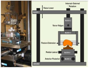
Figure 3-1: LEFT – Posterior view of experimental apparatus. RIGHT- Schematic of experimental
setup for the testing of anteroposterior constraint and internal-external rotational constraint.
Varus-valgus rotation and superiorinferior translation were the only secondary motions
allowed during either AP or IE constraint trials.
3.2.2 Computer Model Development
The experimental testing frame and TKR components were modeled as eight rigid segments, one with a deformable contact layer, using the Software for Interactive Musculoskeletal Modeling (SIMM; Musculographics, Inc.; Santa Rosa, CA) software package. The geometry of each rigid body and model topology was determined from design drawings. Segment masses were either measured or estimated, and inertial parameters were computed from segment dimensions and masses (Table 3-1). Frictional damping within the testing apparatus along the AP, IE, and axial axes was estimated from experimental data and included within the model. Fixture compliance along the vertical testing arm of the loading frame was approximated using a spring scale and ruler and represented by a hinge joint constrained by a linear torsional spring within the model (Figure 3-2; Figure 3-3). The hinge joint axis was located perpendicular to the varus-valgus joint axis. Deflection occurred when a force perpendicular to the long axis of the vertical test arm was applied through cam-spine contact.
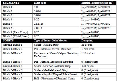
Table 3-1: Computer model segment and joint parameters.
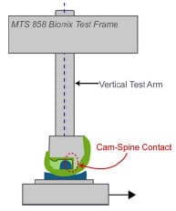
Figure 3-2: Deflection within the vertical testing arm occurred when the tibial post contacted
the femoral cam and produced a transverse force on the testing arm.
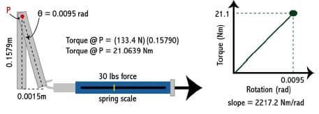
Figure 3-3: A spring scale and ruler were used to measure deflection within vertical testing arm.
A linear torsional spring was used to represent this within the model.
Bearing contact surfaces were described utilizing Rhinoceros 3D solid modeling software (McNeel; Seattle, WA) and custom MATLAB software. Within Rhinoceros, manufacturersupplied computer-assisted design (CAD) drawings of the implants were sectioned into medial and lateral condyle and either cam or spine pieces respectively. Each sectioned piece was transformed into a NURBS surface that approximated the original CAD surface within a tolerance of 0.01 mm. For each NURBS surface a rectangular grid of points was distributed on the surface. Both condyles were represented by a quasi-grid of 150 surface points while the cam and spine were each represented by 400 points. A file containing point locations was exported and a subsequent mesh of rectangular elements created. Eac
h rectangular element had its vertices ordered correctly to ensure that its surface normal vector pointed outwards from the articulating surface. Thus, tibial and femoral surface normal vectors pointed towards one another. B-splines, using centripetal parameterization, were computed for each femoral rectangular element. More than 1100 compressive springs were distributed along the medial and lateral condyles of the tibial contact surface such that the mean area each spring represented was 1.7 ± 0.4 mm². Similarly, more than 1500 springs were distributed across the tibial spine such that the mean area each spring represented was 1.1 ± 0.6 mm². Homogenous spring stiffness and damping values were determined from the mean area computations and from the material properties of ultra high molecular weight polyethylene (UHMWPE) (Piazza, 1998) (Table 3-2).
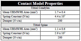
Table 3-2: Properties of spring-damper model used to model the viscoelastic behavior of UHMWPE.
Contact force between bearing surfaces was computed during the simulation using a rigid-body-spring-model (Li et al., 1997). During the simulation, penetration of the B-spline femoral elements into the tibial insert was determined by computing the signed distance of each spring from the closest element. A negative distance represented spring compression. To increase computational speed associated with determining the intersection of each spring with a femoral element, the closest femoral element associated with each spring was stored during each time step and initially checked in the subsequent iteration. If spring penetration did not occur with this element, the surrounding elements were then checked prior to checking all femoral elements. By modeling the viscoelastic nature of UHMWPE as a damper in parallel with a spring (Kelvin-Voight model), contact force could be computed:

where F is contact force, k is the spring constant, x is the spring penetration (compression), b is the damping value, and •x is the penetration velocity. The appropriate contact forces were instantaneously applied to the femoral component. An arbitrary number of tibiofemoral contact points were possible on both condyles and between the cam-spine. Additionally, implants were not constrained to remain in contact throughout the simulation.
The equations of motion were formulated using an advanced Kane’s formulation (Kane and Levinson, 1985) with the SIMM/Dynamic Pipeline (Musculographics, Inc.; Santa Rosa, CA) and SD/FAST (Parametric Tech Corp.; Needham, MA) software packages. A variable time-step 4th order Runge-Kutta-Merson integrator was utilized for the integration of nonlinear equations of motion forward in time. For IE rotary constraint simulations, axial compressive load was modeled as a combined linear and 10 coefficient Fourier time series function, but due to the complexity of applied load during AP drawer trials a 25th order polynomial was required to accurately model the varying axial load (Figure 3-4). Motion, either AP displacement or IE rotation, was modeled as a combination 4th order polynomial and cosine function. A combined approach was required because each experimental trial began from neutral position before being cycled back-and-forth from its predetermined limits. AP drawer and IE rotary laxity tests were simulated with and without fixture compliance of the vertical testing arm to assess its effect on constraint. The appropriate AP starting position for both simulations was determined through a trial-and-error process.
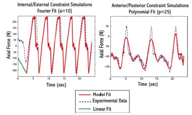
Figure 3-4: Example of model fit to experimental axial compressive load during implant
constraint testing. LEFTA combined linear and Fourier fit was used for internal/external constraint
simulations. RIGHT – A 25th order polynomial was used for anterior/posterior constraint simulations.
3.2.3 Modeling Secondary Degrees of Freedom
The present ASTM test method (2005) of constraint testing does not specify what secondary motions should be free during either AP drawer of IE rotary constraint testing of asymmetrical designs. During an AP drawer test these potential secondary motions include: ML displacement, VV rotation, and IE rotation. During an IE rotational test these include: ML displacement, VV rotation, and AP displacement. To assess the effect of secondary degrees of freedom (DOF) on constraint measurement the aforementioned model was idealized in a number of ways. A consistent compressive axial load of 712 N was applied throughout each simulation. Small damping values were applied at each joint to assure mathematical stability (linear damping < 30 N·s/m; torsional damping < 30 N·s/rad). Simulations of a Duracon Cruciate Retaining (CR) implant (Stryker Orthopaedics; Mahwah, NJ) undergoing an AP drawer and IE rotary laxity test were performed with all secondary DOFs locked, with all secondary DOFs open, and with the remaining 6 combinations of unlocking. For the IE rotary laxity simulations, contact between the condyles was investigated by examining the number of springs that were engaged at each time step to determine if condylar lift-off occurred at any instance during the test. Investigation of model sensitivity to VV joint location within the test frame was simulated by translating this joint center in the SI direction ±5 cm with all secondary motions possible.
3.3 Results
3.3.1 Comparison of Computer Simulations with Experimental Results
When fixture compliance was included within the model at 0º flexion, AP drawer load curves had a qualitatively similar shape and a root-mean-square (RMS) difference of 30.2 N (Figure 3-5). Similar agreement was found between the computed axial displacement of the femoral component and the experimentally measured displacement, with an RMS difference of only 0.09 mm. However, simulations run without compliance of the vertical testing arm required greater force to achieve the same level of posterior displacement. Computed RMS differences for AP drawer load and axial displacement of this simulation were 363.7 N and 3.20 mm respectively.
Favorable agreement was also found between computer model rotary torques and experimentally-measured values for an IE rotary laxity test. Maximum and minimum torque values for simulations run with fixture compliance were 9.1% and 11.2% larger than experimental values, while simulations run without this compliance displayed torques 37.6% and 42.6% greater (Figure 3-6). With regard to axial displacement, the femoral segment simulations with and without fixture compliance had RMS differences of 0.49 and 0.73 mm, respectively, as compared to experimental measurements. Varus-valgus rotations, a secondary motion allowed during both constraint tests, were less than 1º for all simulations, but no comparison to experimental values was possible as this rotation was not recorded during mechanical testing.
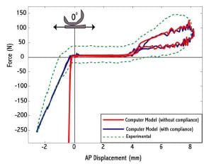
Figure 3-5: Experimentally-measured constraint force (dotted) for an anterior-posterior
drawer test with a posterior substituting implant. A computer simulation including fixture
compliance (blue) matched compared more favorably with experimental values, while a
simulation without this compliance (red) demonstrated stark differences upon cam-spine interaction.
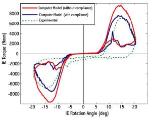
Figure 3-6: Experimentally-measured constraint torque (dotted) for an internal-external
rotary laxity test with a posterior substituting implant. Computer simulations including fixture
compliance (blue) compared more favorably to experimental results than did
simulations without this compliance (red).
3.3.2 Effect of Secondary Degrees of Freedom on TKR Constraint Testing
Unlocking all secondary DOFs reduced the constraint experienced by the PCR implant for an AP drawer test as the tibial insert was posteriorly displaced (Figure 3-7). As the tibial component moved posteriorly and the femoral component encountered the anterior curvature of the tibial insert the all-locked condition required a force 20% higher to reach the same displacement when compared to the all-open configuration. Similarly, every other configuration of unlocking, whether 1, 2 or 3 joints were freed to move, reduced restraint as the femoral component approached anterior subluxation.
Similar trends were demonstrated during simulations of IE rotational constraint (Figure 3-8). Unlocking all secondary DOFs reduced torques for both internal and external rotation by over 3500 N·mm as compared to when these DOFs were locked. Any unlocking configuration produced similar curves with one exception, when only AP motion was allowed. In this simulation, no frontal plane movement was possible and the computed torques comparably more favorably to the all-locked setting.
The combination of secondary motions permitted affected the pattern and magnitudes of secondary motions as well as load sharing between the medial and lateral condyle. For IE simulations with ML freedom, the ML displacements displayed substantially different patterns and magnitudes that were 4 mm larger than when VV motions were simultaneously allowed as opposed to simulations with VV locked (Figure 3-9). For all IE simulations, the total number of contact points on the medial and lateral condyles was also examined. In the two simulations restricting all frontal plane movement (ML and VV) the total number of medial or lateral condylar contact points was zero at some point during the movement sequence (Figure 3-10). No simulations with any frontal-plane DOF unlocked displayed this phenomenon.
A change in VV joint placement in the SI axis had negligible effect on computed AP drawer load or IE rotary torque, but certain secondary motions were sensitive to this translation during IE rotary simulations. Displacement of the joint in either direction caused maximum anterior translations to increase over 2 mm as compared to the original joint location. Translation 5 cm superiorly caused an increase of maximum ML displacements of 1.6 mm as compared to the original joint location, while translation 5 cm inferiorly caused a reduction of these same displacements 1.6 mm.
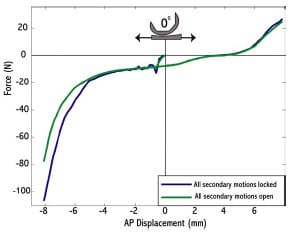
Figure 3-7: Computer model outputs of an anterior-posterior drawer test with two different
locking configurations of secondary degrees of freedom. The simulation with complete freedom of
secondary DOFs displayed decreased constraint as opposed to when all secondary motions were locked.
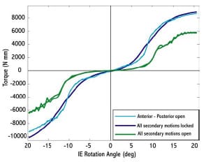
Figure 3-8: Computer model output of torque versus internal-external rotational
angle for three different locking configurations of secondary degrees of freedom (varus-valgus,
anterior-posterior, medial-lateral) of a cruciate retaining implant.
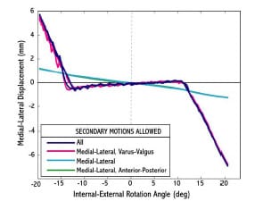
Figure 3-9: Medial-lateral (ML) displacements plotted as a function of internal-external
rotation angle. The combination of secondary motions allowed affected the patterns
and magnitudes ML displacements.
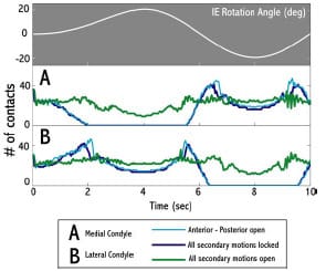
Figure 3-10: The number of medial and lateral condyle tibiofemoral contact points during rotational
constraint simulations for three different locking configurations. Simulations with all secondary motions
locked and with only anterior-posterior motion allowed produced periods of condylar unloading.
3.4 Discussion
Although previous computational models have been used to simulate TKR motion within a constraint test, no other study has validated a PS implant in a range of constraint test with experimental comparison. Experimental artifacts were measured and included within the model because these artifacts altered the constraint properties of the tested implant. During both AP drawer and IE rotary laxity tests the vertical testing arm was subject to forces perpendicular to its long axis. Deflection within this testing arm substantially altered both AP and IE constraint profiles (Figure 3-5, Figure 3-6). Specifically, during the AP drawer test when the posterior aspect of the spine contacted the cam large forces perpendicular to the long axis of the testing arm produced measurable deflection. Although some of this deflection could be due to deformation of the plastic or deformations at the interface between the insert and tibial tray, it is unlikely that these sources accounted for greater than 2 mm of motion. Additionally, including this deflection in the model produced outputs that matched favorably with experimental values.
Investigation into the effect of secondary motions on measured constraint yielded consistent results for both laxity simulations. Unlocking all secondary DOFs substantially reduced the measured constraint as compared with the all-locked condition. In general, allowing either one or two secondary motions produced similar results as to the all-open configuration. The only exception to th
is trend was an IE rotary simulation with only AP motion allowed. The elimination of all frontal plane motion (VV, ML) caused an increase in required torque and condylar lift-off. These simulations reaffirm the recommendation of Haider and Walker (2005) that all secondary DOFs should be unrestricted during constraint testing. If it is only AP drawer load versus displacement and IE rotary torque verus angle curves that are required, then unlocking of the ML joint would produce similar results as the all-open configuration. This may be an attractive alternative when designing a test frame because including a VV joint within a test frame may be of increased difficult.
Haider and Walker (2005) indicated that implants displaying anomalous constraint profiles could potentially be distinguished by examining coupled secondary motions, but the present ASTM standard does not specifically delineate a testing procedure including secondary DOFs. The present study showed that the pattern and magnitude of these coupled secondary displacements and rotations were altered by the particular unlocking configuration (Figure 3-9). For instance, during an AP drawer test more than 5 mm of ML displacement occurred when all secondary DOFs were open as opposed to only 1mm when only ML displacements were allowed. Secondary motion outputs during IE rotary simulations were also found to be sensitive to the location of the VV joint location indicating that the initial design of a test frame can ultimately affect coupled secondary motions.
The rationale of a uniform protocol for laxity testing is the standardization of testing conditions to allow an unbiased comparison of total knee implants tested by different investigators. Surgeons could then match the laxity needs of a specific patient with the passive constraint provided by a particular implant’s design (ASTM International, 2003). Although a standard test method does improve the possibility of objective comparison between constraint profiles of different implants, artifacts present within experimental setups, variety of test frame designs, and the lack of a clearly defined secondary DOF protocol pose substantial challenges.
Computational prediction of constraint within TKR implants has certain advantages over experimental testing. Dynamic computer models require only a few minutes of CPU time to simulate a laxity test and can eliminate experimental artifacts that may alter the true constraint pattern of an implant. Although computational models should never replace experimental testing, models can be used to expedite the design cycle and objectively compare different implants. Presently, with the numerous means of implementing constraint tests (Haider and Walker, 2005), a computer model may be the only feasible methodology for unbiased implant comparisons.
A number of limitations should be noted regarding the models developed for this study. Frictional forces were not included in either model despite the fact that these forces have been shown to alter TKR motions (Sathasivam and Walker, 1997). This could explain the discrepancy between computed AP drawer load and measured values (Figure 3-5). Several model parameters (segment mass, inertial terms, and joint damping) (Table 3-1) were estimated because physical measurements were not possible, but further analyses revealed that model output was not sensitive to their selection. It was speculated that since the simulation movement speed was slow, their effect on computed constraint was minimal. Although the initial development of a dynamic model is more time consuming than a static model, a static modeling approach was not adopted because of the complexity of determining implant contact forces at each time interval. Although the contact model employed permits small UHMWPE deformations, it does not consider permanent plastic deformation that may occur from high stress. Micromotion between the tibial insert and surrounding tray was not modeled, although this motion is known to occur (Wasielewski et al., 1997) Because model output was sensitive to starting AP position for both constraint simulations, an iterative approach was adopted to determine the appropriate starting position.
The ability to quantify the AP and IE constraint of a TKR implant based upon its geometry alone is critical to understanding how it will perform in vivo. A computational approach has been shown to accurately predict this constraint. Experimental validation of this type of model was necessary before more complicated models of implant function within a patient can be developed. Future work will be directed at computationally predicting constraint in numerous TKR implants, both PS and CR design, at clinically relevant flexion angles. Dynamic computer models of TKR motion used in conjunction with experimental testing can potentially drive more meaningful research questions and understand the complex interaction between implant design and function.
3.5 Acknowledgments
The study was funded through the Matching Dissertation Grant from the International Society of Biomechanics and through the Academic Computing Fellowship (Pennsylvania State University). Safia Bhimji and Joseph Racanelli (Stryker Orthopaedics; Mahwah, NJ) collected experimental data and assisted with measuring model parameters.
CHAPTER 4 – COMPUTATIONAL ASSESSMENT OF ANTEROPOSTERIOR LAXITY FOLLOWING PARTIAL PCL RELEASE AND INCREASING TIBIAL SLOPE IN CRUCIATE-RETAINING TKR
4.1 Introduction
Although the orthopedic community remains divided regarding the retention of the posterior cruciate ligament (PCL) (Saleh et al., 2000), it is generally accepted that proper PCL tension is a requirement for normal functioning following cruciate retaining total knee replacement (PCR) (Haas and Saleh, 2001). It has been argued that retention of the PCL achieves more normal knee kinematics, a more stable joint, improved joint load distribution, and a more efficient extensor mechanism by producing posterior translation of the femur on the tibia (femoral rollback) (Sorger et al., 1997). Proponents of retaining the PCL cite more normal gait patterns and increased quadriceps efficiency as two of the major reasons to routinely salvage the PCL (Andriacchi and Galante, 1988; Ishii et al., 1998).
The PCL has a proximal attachment within the intercondylar notch on the femoral medial condyle and a distal attachment approximately two centimeters distal to the posterior joint line (Ritter et al., 1988). Due to the orientation of its fibers the PCL provides the primary restraint to posterior tibial translation with respect to the femur (Race and Amis, 1996). Noyes et al. (1993) found that the PCL provides 95% of this restraining force. As a result of its orientation relative to the knee center of rotation, the PCL tightens during flexion and increases anterior-posterior (AP) stability at higher flexion angles. The PCL also provides secondary stabilization to varusvalgus laxity.
Modification of the joint line through inaccurate bony cuts can affect PCL tension and consequently alter its strain patterns following TKR. Joint line elevation, resulting from excessive resection of femoral bone and insufficient removal of bone from the proximal tibia, is a common occurrence. It was reported by Daluga et al. (1991) that a range of 4.0-8.9 mm elevation can be expected clinically. This elevation could alter the resting slack length of the PCL causing ligament strains above or below normal values. Lotke et al. (1993) found that only 1 of 10 knees following PCR had normal strain patterns. Posterior positioning of the femoral component can also contribute to excessive PCL tension (Nagamine et al., 1994). PCL tension is also dependent on the posterior geometry of femoral and tibial components (Arima et al., 1998). Inappropriately sized components as compared to the native bony geometries can alter PCL strains during flexion. An overly taut PCL in deep flexio
n can compromise knee joint kinematics by (1) restricting AP range of motion (ROM), (2) causing excessive rollback and (3) reducing maximum flexion.
In cases where PCL tightness limits flexion ROM, a partial PCL release has been advocated to reduce ligamentous tension (Ritter et al., 1988; Scott and Thornhill, 1994; Williams et al., 1996; Arima et al., 1998; Mihalko and Whiteside, 2003; Yamakado et al., 2003; Nabeyama et al., 2003). Partial release of PCL fibers is intended to diminish the posterior force acting on the femur, reduce rollback and ultimately restore normal knee flexion. Arthroscopic release is performed in 1- to 2-mm sections until a smooth flexion arc is achieved (Nabeyama et al., 2003). Although arthroscopic PCL releases have been described at both tibial and femoral insertion sites, Arima et al. (1998) found no functional differences between the procedures in terms of the resulting AP displacements in a cadaveric study. Incavo et al. (1994) warned that it may be difficult, in practice, to know how much release is warranted and that errors may excessively slacken the PCL leaving the knee prone to AP instability. Despite this practical concern, clinical outcome studies have typically reported good results following partial PCL release (Ritter et al., 1988; Williams et al., 1996; Nabeyama et al., 2003).
Modifying the slope of the proximal tibia bone cut has also been advocated to reduce PCL tensions and maximize flexion (Takatsu et al., 1998). It has been hypothesized that PCL and collateral ligament tensions may be reduced by removing more posterior than anterior tibial bone. This tension reduction would promote normal femoral rollback, increase AP laxity, and permit more knee flexion. Although increasing the tibial slope appears to reduce PCL tension and permit greater flexion, the magnitude of slope required to elicit positive outcomes is subject to debate. Bellemans et al. (2005) reported that, on average, one degree of tibial slope would increase knee flexion by 1.7º. Matsuda et al. (1999) reported that the slope of the natural tibial plateau was highly variable across subjects and they recommended that the angle of this cut should be decided on a case-by-case basis. Singerman et al. (1996) reported that PCL strain was significantly reduced when the posterior slope was increased from 5º to 10º in 7 cadaveric knees. In contrast, Whiteside and Amador (1988) found that a 3º posterior slope gave optimal joint stability in flexion and extension and that, while larger slopes increased AP laxity, they also created joint instability.
Few biomechanical studies have been performed to investigate the effect of a tight PCL on joint stability and range of motion (Arima et al., 1998; Jojima et al., 2004). Although the presence of a tight PCL can compromise TKR function, there does not appear to a consensus regarding its treatment. In a study of 12 cadaver specimens Arima et al. (1998) found that AP laxity increased at all tested flexion angles following TKR with partial PCL release. The use of a flat tibial insert did not increase these displacements. Arima et al. (1998) concluded that partial PCL release may improve knee function without the fear of AP instability. A recent study of 5 cadaver knees examined the effect of partial PCL release or sloping of the tibial component on AP laxity measurements (Jojima et al., 2004). Jojima et al. (2004) found that partial PCL release appeared to relieve ligament tension, however, tibial sloping was found to improve range of motion more. Because tibial sloping was able to address tightness within the collateral ligaments, rotational laxity was also improved.
The purpose of the present study was to investigate the combined effect of PCL treatment and tibial sloping on AP laxity using a computational model. Simulations with both a condylar and an ultra-conforming tibial insert were assessed to determine if conformity of bearing surfaces would alter AP laxity. Based upon the findings of Jojima et al. (2004), it was hypothesized that increasing tibial slope would be more effective at increasing laxity than partial PCL release, but it was uncertain as to the magnitude of slope that would be required. In regard to insert design, it was hypothesized that an ultra-conforming insert would provide more constraint at all flexion angles, especially when the PCL anterolateral bundle was either partially or fully released.
4.2 Methodology 4.2.1 Computer Model Overview
A previously developed forward-dynamic computer simulation of the American Society for Testing and Materials protocol for testing AP constraint (ASTM F1223-05) was found to compare well with experimental results obtained for PS knee components (Chapter 3). The equations of motion were formulated and integrated forward in time using the Software for Interactive Musculoskeletal Modeling (SIMM)/Dynamics Pipeline (Musculographics, Inc.; Santa Rosa, CA) and SD/FAST (Parametric Tech Corp.; Needham, MA) software packages. Computer-assisted design (CAD) drawings of a Duracon Cruciate Retaining (CR) (Stryker Orthopaedics; Mahawah, NJ) total knee design with a condylar and ultra-conforming tibial insert were simulated in this study (Figure 4-1). The ultra-conforming tibial insert, designed for use with or without the PCL, provides greater AP constraint than the condylar insert because of an increase anterior curvature. Both tibial inserts were designed with a built-in 2º posterior tibial slope. Processing of implant surfaces to rectangular meshes has been previously described (Section 3.2.2). Medial and lateral femoral condyles were partitioned into 150 element meshes, while the condyles of each insert were represented by over 1100 damped spring elements. A rigid-body-spring model was utilized to compute articular contact forces throughout the simulations (Li et al., 1997).
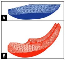
Figure 4-1: Sagittal profiles of the two tibial inserts simulated within this study:
(A) condylar and (B) ultraconforming
4.2.2 Posterior Cruciate Ligament Model Representation
It has been reported that the PCL is composed of an anterolateral (AL) and a posteromedial (PM) bundle (Girgis et al., 1975; Race and Amis, 1996; Harner et al., 1999). Due to its insertion relative to the flexion axis, the AL bundle is lax in extension and tightens with flexion, while the PM bundle is taut in extension and lax in flexion (Girgis et al., 1975). The model incorporated seven non-linear elastic elements representing the AL bundle and four nonlinear elastic elements representing the smaller PM bundle. Although Mommersteeg et al. (1996) found that ligament models with more than seven elements suffered from mathematical redundancy, the present ligament model was used to simulate small fiber releases.
Ligament insertion sites were determined from literature descriptions (Racanelli and Drez, 1994; Morgan et al., 1997; Harner et al., 1999). In order to locate ligament insertions in the correct orientation relative to the femoral component, a medium-sized Duracon CR CAD file was visually placed on a lower extremity SIMM model (Delp et al., 1990) with a femur that was re-digitized for improved resolution (Arnold, 1999). Ligament insertions were placed relative to anatomical landmarks (femoral intracondylar notch and tibial plateau) as described by the aforementioned references (Table 4-1). The total PCL femoral insertion area was estimated by computing the area of the two-dimensional area of the polygon formed from connecting the eleven elastic elements comprising the PCL (Figure 4-2). The computed area fell within the range provided by Harner et al. (1999). Ligament length patterns were determined for each elastic element by applying the tibiofemoral kinematics repo
rted by Walker et al. (1988). Ligament lengths were compared with values reported from in vitro studies (Saddler et al., 1996; Ahmad et al., 2003).
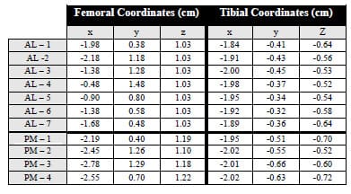
Table 4-1: Local coordinates are provided for both the anterolateral elements
(AL 1-7) and the posteromedial elements (PM 1-4).
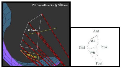
Figure 4-2: LEFT – Sagittal view of femoral locations of the anterolateral (AL) and posteromedial
(PM) ligament bundle in a SIMM model. RIGHT – Image from Harner et al. (1999). Total femoral insertion
areas compared favorably to values reported by Harner et al. (1999)
A quadratic force-elongation function was utilized to model the elastic properties of each element representing the PCL (Wismans et al., 1980; Essinger et al., 1989):

where fj was the force in spring element j, kj was the spring stiffness, and 0j l was the slack length (length at which no force was produced). Elements of each functional bundle were assigned the same stiffnesses. Stiffness for each ligament bundle were taken from Trent et al. (1976) to simulate a “normal” PCL (Table 4-2) .
For normal PCL simulations, the slack length of each AL and PM element was its length at 30º flexion. Fukubayashi et al. (1982) reported the greatest AP laxity at 30º flexion, indicating a potential for cruciate ligament slackness. Verification of an appropriate slack length was accomplished by comparing resultant PCL force during an AP drawer test to experimental results reported by Markolf et al. (1993). For tight PCL simulations, slack length values were reduced 10% for the AL bundle and 5% for the PM bundle (Table 4-2). This essentially shifted the operating portion of a ligament’s force-elongation curve to the right. Since it is not expected that stiffness characteristics would be altered following TKR, these parameters were held constant. The model was sensitive to this reduction of slack length so to verify their selection PCL forces during an AP drawer test were computed and compared to values computed for a normal PCL and from experimental values.
For simulations involving a released AL bundle, elastic elements representing the AL bundle were effectively removed from the model by changing their stiffness values to zero. Three treatments of AL bundle release were modeled to correspond to the iterative approach that occurs during surgery. The first release deleted two elastic elements and the second release deleted two subsequent elements. The third treatment simulated complete release of the AL bundle, as all fibers were removed. The ordering of AL fiber deletion was possible by placing the model in 90º of flexion and eliminating the AL fibers with the most exposed tibial anterior attachment as visualized in SIMM.
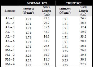
Table 4-2: Stiffness constants (N/mm²), elastic modulus, and slack lengths (cm) are provided
for elastic elements representing the anterolateral (7 elements) and posteromedial (4 elements) bundles
for both normal and tight PCL simulations.
4.2.3 Simulations
Clinical AP laxity is typically measured by applying a 70 N force to the tibia in both the anterior and posterior directions. These laxity assessments are usually conducted with minimal joint loading to minimize the contribution of bearing surfaces to AP laxity. In the present model prescribed, the AP displacement of the tibial insert was prescribed at a rate of 3.4 mm/sec. During the simulation the femoral component was held fixed at a particular flexion angle. The femoral component was free to axially displace and to rotate about varus/valgus and internal/external axes. To permit investigation of the contribution of component congruity and PCL force to resisting AP motion, a constant 200 N compressive axial force was applied. Medial-lateral displacements of the tibia were restricted during each simulation to replicate the experimental procedure of Arima et al. (1998). Small damping values were applied at all other secondary joints to enhance mathematical stability (< 1 Ns/m). The AP force required to move the tibial insert through the prescribed displacement pattern was computed at each time step. In order to compute AP laxity measures from simulation results a MATLAB program was written that fit AP displacement and AP force versus time curves with cubic spline interpolations. AP displacements that corresponded to forces of 70 N, -70 N, and 0 N were used to calculate anterior laxity, posterior laxity and neutral position (Figure 4-3). Since model outputs were at discrete 0.04 second intervals, spline interpolation was required for continuous force versus displacement data.
AP laxity test simulations were run at flexion angles of 0º, 15º, 30º, 45º, 60º, 75º, and 90º for both tibial inserts for a normal and tight PCL. All remaining simulations were conducted with a tight PCL. At each flexion angle a set of simulations was run with an intact tight PCL, two levels of AL-PCL release, and complete AL-PCL release at 0º posterior tibial slope. Each set of simulations was repeated at 2º, 4º and 6º posterior tibial slope for both tibial inserts respectively. To assess the sensitivity of model output to certain ligament parameters that were derived from literature, an analysis was systematically performed on elastic element insertion sites and stiffness constants at 0º flexion. Femoral insertion sites were varied ± 2mm in four directions: anterior, posterior, superior and inferior while the tibial insertions sites were held constant. The tibial insertion sites were also varied in four directions: anterior, posterior, superior and inferior while the femoral insertion sites were held constant. Stiffness constants for the AL bundle were altered ±0.29 N/mm² while the PM bundle stiffness was held constant. Stiffness constants for the PM bundle were altered ±0.75 N/mm² while the AL bundle stiffness was held constant.
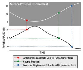
Figure 4-3: Cubic spline interpolations were fit to anterior-posterior displacement and
force curves. Anterior and posterior laxity measures were determined by finding the AP displacement that
corresponded with ±70 N AP force. Neutral point was similarly found from the displacement at 0 N force.
4.3 Results
4.3.1 Intact PCL Simulations
For a normally-tensioned PCL, ligament forces from an AP drawer test were within 50 N as those values
reported by Markholf et al. (1993) (Figure 4-4). Forces in the tight PCL were increased on average 91% as compared to the normal simulations. Averaged across all flexion angles a tight PCL reduced AP laxity by over 3.5 mm (Figure 4-5). Normal AP laxities at flexion angles greater than 30º compared favorably to experimental values reported by Arima et al. (1998). Although PCL tensions were higher and AP laxities reduced as compared with a normally tensioned PCL, there were minimal differences in neutral point location across all flexion angles.
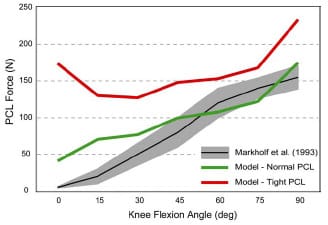
Figure 4-4: Model PCL force as the result of a posterior 50N force was computed for normal and tight
ligament values at each flexion. Model output was compared to experimental values (Markholf et al., 1993).
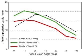
Figure 4-5: AP laxity simulations of a tight PCL reduced displacements by an average over 3.5mm across
all flexion angles. A normally tensioned PCL produced comparable results to those reported by Arima et
al. (1998) for angles above 30º.
4.3.2 Effect of Partial PCL Release
Selective partial release of the AL bundle fibers increased anterior displacement at all flexion angles except 0º for a condylar insert regardless of posterior tibial slope (Figure 4-6). PCL tension was reduced 29% and 41% at 90º flexion by successive partial release of the AL bundle. Although partial release was effective at increasing anterior laxity, displacement was less than that computed for a normal PCL. Only when a complete release of the AL bundle was simulated did anterior displacements exceed these simulated for a normal PCL. In terms of posterior displacement, release of the AL bundle produced minimal increase at all flexion angles with the exception of 90º. The neutral position at each flexion angle was only minimally affected as it moved slightly anterior (~1 mm) from a tightly tensioned PCL to a complete AL bundle release (Table 4-3). Neutral point locations following a complete AL bundle release were within 1 mm at all flexion angles as compared with simulations involving a normal PCL.
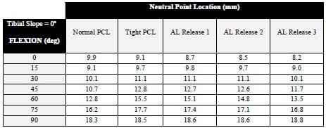
Table 4-3: Neutral point locations (mm) for a condylar tibial insert with 0º posterior slope
with a normal and tight PCL, and three treatments of the AL bundle (2/7, 4/7, and full release).
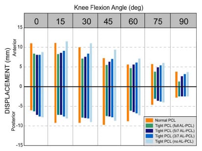
Figure 4-6: Partial release of a tight anterolateral PCL bundle increased anterior and posterior
displacement at nearly all flexion angles with a condylar insert. Zero on the y-axis
refers to neutral point for that simulation only.
4.3.3 Effect of Posterior Tibial Slope
Increasing posterior tibial slope of the conylar tibial insert increased anterior laxity across flexion angles (Figure 4-7). A 6º posterior tibial slope reduced PCL force by 36% compared with the 0º slope condition, and anterior laxity was increased by 2.0 mm. Only at 15º flexion did any sloping condition produce anterior laxity that exceeded the normal displacement value. Neutral point position was substantially affected as the posterior sloping was increased. For all flexion angles the neutral point was over 2 mm posterior compared with the 0º slope simulations (Figure 4-8). At 75º flexion with a 6º slope the neutral point was 5.1 mm posterior to its location with no tibial sloping. As a result of this posterior positioning the posterior laxity was reduced with increasing slope (Figure 4-7). In fact, at flexion angles 45º and greater with 4º and 6º tibial slopes the limit of the insert was reached prior to the development of a 70 N force. As a result of the decreased posterior travel the overall AP laxity for a 6º tibial slope was similar to the original tight PCL values. Posterior instability was present in simulations run with an ultra-conforming insert as well, and anterior displacements were reduced with the more conforming design.
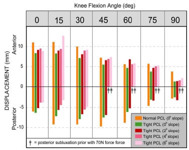
Figure 4-7: Increasing posterior tibial slope was effective at increasing anterior laxity across all
flexion angles with a condylar tibial insert. The potential for posterior instability occurred for flexion
angles of 45º and higher with 4º and 6º tibial slopes.
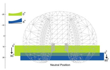
Figure 4-8: Schematic demonstrating neutral position differences between 0º and 6º posterior tibial
slope. A 6º tibial slope reduced the overall travel of the neutral position as compared to the 0º slope
condition, and it also placed the neutral point near the posterior edge of insert at 90º.
4.4 Discussion
Both partial PCL release and increasing posterior tibial slope have been advocated for the treatment of a tight PCL following cruciate retaining TKR procedures (Arima et al., 1998; Jojima et al., 2004). Although both methods have been shown to provide effective reduction of PCL tension accommodating greater flexion and improved joint laxity characteristics, it was unclear which treatment was more effective at restoring normal knee stability patterns. The present computer model sought to investigate the relationship between varying magnitudes of both partial AL bundle release and increasing posterior tibial slope on AP laxity.
Partial AL bundle release was effective at increasing AP displacement and moving the neutral point anteriorly. At flexion angles 15º and higher selective release of fibers produced a substantial increase in anterior laxity (Figure 4-6). Posterior displacement values for all partial release simulations were smaller than those experienced with a normal PCL because of the posterior position of the neutral point. The neutral point was determined by the AP location that corresponded to a zero AP force (Figure 4-3). If the neutral point is posteriorly positioned, then upon application of an anterior force to the tibia the insert’s posterior curvature would be contacted sooner. This effectively reduces the amount of posterior travel that can occur
before the curvature of the insert resists the applied motion. Selective release of the AL bundle moved the neutral point anterior and subsequently increased posterior laxity.
Increasing posterior tibial slope was effective at reducing PCL tension and increasing anterior laxity, but overall AP laxity was diminished because of an overall posterior shifting of the neutral point (Figure 4-8). Posterior displacements were substantially reduced as a result of a posterior neutral point and an effective reduced curvature of the posterior lip of the insert. If the posterior lip is thought of as a hill that the femoral component must ride up as the tibia is moved anterior, then posterior sloping effectively lowers the overall pitch and height of the hill. This combined effect caused the potential for posterior instability at flexion angles 45º and greater with posterior tibial slopes of 4º and 6º. The presence of an ultra-conforming insert only provided marginal gains in addressing this instability because the two designs differ only slightly in their posterior curvatures. Although posterior subluxation is a rare clinical finding occurring in less than 0.25% of TKRs, Yamakado et al. (2003) attributed a tight PCL and increased posterior tibial slope as potential risk factors.
As the tibial slope was increased, the neutral position was shifted to the posterior edge of the insert and overall travel of the neutral point was reduced by over 2 mm compared with the travel simulated with a normally tensioned PCL. Reduced travel of the neutral point as a result of increased tibial slope has wear implications. Wasilewski et al. (1994) found that in 17 of 29 knees that displayed wear tracks in the posterior section of the retrieved insert the average tibial slope was 8.8º as compared to 5.9º in inserts not displaying these wear tracks. Increasing posterior tibial slope may also contribute to AP sliding that would increase the likelihood of UHMWPE wear (Wasielewski et al., 1994; Blunn et al., 1997).
Computer model results compared favorably with in vitro studies investigating the same issues and measuring AP laxity in a similar fashion. Arima et al. (1998) reported a increase in AP laxity of less than 2.6 mm at all flexion angles following a partial PCL release in 12 cadaveric knees. For the present study a release of 4/7 of the AL bundle produced a mean increase in 1.9 mm and a full release of the AL bundle release produced a mean 3.9 mm increase. Jojima et al. (2004) reported similar values for a partial release in a series of 5 cadaveric knees. However, model results regarding increased posterior tibial sloping did not agree with Jojima et al. (2004). They reported substantial gains in AP laxity resulting from a 4º tibial slope. A probable cause for this discrepancy is that the present model included a compressive axial force of 200N during the AP drawer test while Jojima et al. (2004) performed their draw test with the joint unloaded because they sought to investigate restraint provided from ligament tension and not component congruity. Although increasing tibial slope does reduce PCL tensions, it also increases the anterior slope that restricts anterior laxity.
A number of limitations should be noted regarding the model developed for this study. Although other soft tissues crossing the joint may contribute to secondary restraint of AP motion, only the PCL was modeled. This may explain why a 70 N anterior force was sufficient to cause dislocation when the tibial slope was 4-6º at flexion angles greater than 45º. In addition, frictional forces were not included in this model despite the fact that these forces have been shown to alter TKR motions (Sathasivam and Walker, 1997). Simulation of a tight PCL required the alteration of AL and PM bundle slack length parameters, although these values could not be experimentally verified. The PCL was modeled as two functionally independent bundles, but Makris et al. (2000) have suggested that the PCL may be more accurately comprised of four functional bundles.
In conclusion a computer model was developed to investigate two treatment protocols for a tight PCL. Although both partial PCL release and increasing posterior tibial slope were effective at reducing tension, only a partial PCL release treatment was able to retain a neutral point similar to a normally tensioned PCL. As a result, partial PCL treatment was able to improve overall AP laxity without increasing the chance for posterior insert wear and posterior subluxation. Although some posterior tibial sloping may be warranted for soft tissue balancing other than the PCL, increased posterior tibial slope has been associated with poor clinical outcomes (Bellemans et al., 2005). Balancing the PCL during TKR through a partial release technique requires increased surgical skill and precision, but the results of this study indicate that it is effective at increasing AP laxity without the risk of posterior instability that may accompany an increased tibial slope.
CHAPTER 5 – EFFECT OF PATELLAR HEIGHT ON EXTENSOR MECHANISM IN TKR
5.1 Introduction
Complications associated with the patellofemoral joint are the leading causes of poor results following total knee replacement (TKR) (Petersilge et al., 1994; Colwell, 2003). These complications include patellar fracture, subluxation, polyethylene wear, implant fracture, dislocation, patellar tendon rupture, and quadriceps tendon rupture (Mochizuki and Schurman, 1979). In a study of retrieved TKR implants, 44% of patellar components had severe wear patterns (Colizza et al., 1995). Although the exact etiology of patellofemoral complications is dependent on a number of factors, increased contact pressures and decreased contact areas are the common outcomes (Glaser et al., 1999).
Patellar positioning in the sagittal plane relative to the femoral trochlear groove has direct implications for knee joint mechanics, patellar tendon strains, patellofemoral stress, and knee extension efficiency. Abnormal distal positioning of the patella, patella baja, can be classified into two groups: congential and acquired (Chonko et al., 2004). Acquired patella baja is the result of trauma and/or surgery. Acquired patella baja could result from any of the following conditions: (1) shortened patellar tendon, (2) distal position of the patella relative to the femoral trochlear groove, and (3) reduced distance between the inferior patellar pole and tibial plateau (Grelsamer, 2002). Following TKR, the patellar height may be reduced as a result of patellar tendon scarring or surgical technique. Abnormal distal patellar height following TKR may cause (1) a decreased extensor moment arm, (2) increased risk for patellar or quadriceps tendon rupture, (3) patellar entrapment within the trochlear groove (Meyer et al., 1997), (4) impingement of the polyethylene patellar component and the tibial insert, (5) anterior knee pain and/or (6) difficulty with movement following TKR (Chonko et al., 2004).
Shortening of the patellar tendon length due to scarring is common following TKR (Koshino et al., 1990; Weale et al., 1999). Patellar tendon shortening can occur through shrinkage of the tendon or adhesion of the tendon to the anterior tibia (Chonko et al., 2004). The operative procedure of knee joint replacement creates a substantial injury to the soft tissues surrounding the joint. It has been reported that intraoperative strains in the collateral ligaments exceed 20% (Atkinson et al., 2001). Although the cause of shortening was not identified, Koshino et al. (1990) reported that the patellar tendon length shortened more than 10% following TKR in 61 of 94 knees. The authors speculated that tendon shortening developed “more in cases with vigorous quadriceps exercise”. Similarly, Weale et al. (1999) reported a 10% shortening of the patellar tendon length in 34% TKR patients at a five year follow-up. The authors speculated that patients undergoing a lateral so
ft tissue release are at an increased risk for patellar tendon shortening following TKR.
Inaccurate bony cuts are common during TKR procedure and can result in joint line elevation ranging from 2-8 mm (Carpenter et al., 1994). The joint line can become elevated when the polyethylene tibial insert is thicker than the tibial bone that was removed. Excessive resection of the distal or posterior femur would require a larger polyethylene tibial insert to balance the resulting gap between the components in flexion or extension. As a result of an elevated joint line the patella may appear to be abnormally distal on postoperative radiographs. Grelsamer (2002) termed this condition “pseudo patella baja” because the patellar tendon length has remained constant but the tibial joint surface has been moved proximally (Figure 5-1) . Joint line elevations greater than 8 mm have been found to be associated with patellofemoral complications (Figgie et al., 1986). Pseudo patella baja can also result from distal placement of the patellar component on the residual patellar bone.
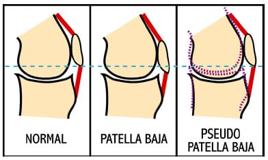
Figure 5-1: Schematic illustrating the physical differences between the true presentation of patella
baja and the pseudo patella baja condition. True patella baja has a shortening of the patellar tendon, while
in the pseudo patella baja condition the patellar tendon length remains consistent. Note that, the
superior-inferior position of the patella relative to the horizontal reference (dashed blue line) remains
consistent between the normal and pseudo patella baja conditions. The dashed purple lines
represent joint line elevation following TKR.
Investigators have extensively studied the biomechanics of the patellofemoral joint in TKR, but few studies have addressed either patellar tendon shortening or joint line elevation. No study has simultaneously addressed both of these issues. Meyer et al. (1997) investigated patellar contact stress in a knee cadaver model that simulated patella baja through distal positioning of the tibial tubercle. Although the investigators reported these simulations as patella baja conditions, according to Grelsamer’s definition (2002) these simulations are more properly classified as pseudo patella baja because patellar tendon length was not shortened. Distal shifting of the tibial tubercle moved the patellar contact areas proximally and overall contact areas were reduced with increased extent of pseudo patella baja. A similar in vitro study by Muellner et al. (2003) shortened the patellar tendon length by suturing the patellar tendon to holes drilled through the inferior pole of the patella and tibial tubercle. A 20% reduction in patellar tendon length did not significantly alter patellar orientation as compared to the original tendon length. Patellar orientation was measured using magnetic resonance imaging (MRI) techniques with the cadaver knee in static poses, but it is possible that a dynamic movement simulation would have elicited differences in patellar orientation not apparent in a static analysis. Singerman et al. (1994) investigated the sensitivity of patellofemoral contact force to sagittal positioning of the patella using a cadaver model. Patellar height was altered in a fashion similar to that employed by Meyer et al. (2003). The investigators reported that the point application of contact force moved superior with increased severity of pseudo patella baja.
Numerous analytical studies have investigated patellofemoral mechanics (van Eijden et al., 1987; Hirokawa, 1991; Hefzy and Yang, 1993; Heegaard et al., 2001), but none of these has investigated the mechanical differences between patella baja and pseudo patella baja within TKR. van Eijden et al. (1987) developed a planar model of the patellofemoral joint to investigate the effect of patellar tendon length on joint mechanics. The patellofemoral contact point moved superiorly with a shortened patellar tendon. Tibial anterior-posterior (AP) force was sensitive to the angle formed between the patellar tendon and the tibial long axis, but the quadriceps moment arm was not sensitive to this parameter. A shortened patellar tendon increased this angle and subsequently increased the tibial AP force by 17%. Hirokawa (1991) developed a three-dimensional quasi-static model of the patellofemoral joint to investigate two different mechanisms of patella baja: 1 cm patellar tendon shortening (simulating physical tendon shortening) and 1 cm anterior displacement of the tibial tubercle (simulating tendon adhesion to the anterior tibia). Patellofemoral joint contact stress, a model output, was not sensitive to tendon shortening but showed 20-30% reduction of stress over the range of motion when the tibial tubercle was moved 1 cm anterior.
Despite many experimental and computational studies investigating patellofemoral mechanics in normal and TKR knees, no study has investigated the mechanical differences between patella baja and pseudo patella baja. Although it is speculated that both patellar height conditions result in diminished extensor mechanism efficiency, the exact mechanism by which each alters knee mechanics is unknown. The primary objectives of the present study were (1) to compare the required quadriceps force to extend a mechanical TKR model within a dynamic knee simulator between two patellar height conditions (patella baja and pseudo patella baja), and (2) to investigate whether an anatomical or symmetric patellar insert design influences quadriceps efficiency. A second objective of the present study was to develop and verify a computational method for determining implant contact based upon measured kinematics. Based upon clinical findings it was hypothesized that both patellar height conditions, regardless of patellar implant design, would have detrimental effects on the extensor mechanism as compared to normal patellar positioning, but is was unclear as to the exact manner how each condition would alter patellofemoral kinematics.
5.2 Methodology 5.2.1 Mechanical TKR Simulator
A dynamic mechanical TKR simulator was employed because it allowed the ability to precisely alter both the patellar tendon length (patella baja) and joint line position (pseudo patella baja) for a dynamic squatting simulation (Figure 5-2). The mechanical TKR model incorporated a medium-sized Duracon Posterior Stabilized knee implant (PS) (Stryker Orthpaedics; Mahwah, NJ) that featured a cam-spine mechanism to replace the function of the posterior cruciate ligament. An 11-mm thick symmetric dome shape and an 11-mm thick anatomically-shaped polyethylene patellar implant (Stryker Orthopaedics; Mahwah, NJ) were tested in this study.
A more thorough description of the mechanical TKR simulator used within this study is provided in Appendix C. The mechanical knee model was designed with a 7º quadriceps angle that caused the long axis of femur to pass through the medial-lateral (ML) midpoint of the tibiofemoral articulating surface. The quadriceps angle is the angle formed by the vectors connecting the midpoint of the patella and the (1) anterior superior iliac spine and the (2) tibial tubercle. The total femoral segment length, from joint line to greater trochanter, was designed to be 43 cm to approximate a medium-sized male. The tibial insert was rigidly fixed to the tibial se
gment through an anterior and posterior locking mechanism at a manufacturer-recommended 3º posterior tibial slope. The tibial insert was centered in the anterior-posterior (AP) and ML directions relative to the long axis of the tibia. The total tibial segment length, from joint line to malleolar height, was designed to be 43 cm to approximate a medium-sized male. The tibial tubercle could be altered in both the AP and superior-inferior (SI) directions. The patellar components were press-fit on a custom designed aluminum block approximating the residual patellar bone. The total patellar thickness was 23.6 mm, in agreement with the mean unresected patellar thickness in a study of 337 knees as reported by Hitt et al. (2003). The residual patella was approximately 36 mm in length, as the inferior pole of the patella was included in the design. The patellar components had identical sets of pegs extending from their non-articulating side, facilitating interchange of the patellar components during the experimental protocol. The only soft tissues included in the model were the quadriceps and patellar tendon. Nylon webbing (Jontay Distributor; Waycross, GA) was used to represent the patellar tendon and quadriceps tendon. Uniaxial tensile testing was performed in a servohydraulic materials testing machine (MTS Systems Corp.; Eden Prairie, MN) to ensure that the webbing had similar stiffness values as those reported for the patellar and quadriceps tendons (Appendix C).
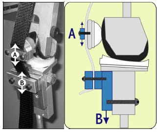
Figure 5-2: The mechanical TKR model allowed the patellar height to be reduced through shortening
patellar tendon length by moving A superior and inferior (patella baja). It also could be adjusted by moving
the tibial tubercle (B) superior and inferior (pseudo patella baja).
5.2.2 Dynamic Knee Simulator A more thorough description of the dynamic knee simulator used within this study is provided in Appendix B. A custom-designed apparatus for simulating knee function (Cain, 2002) was modified to simulate a squatting movement. The rig was designed with ball-andsocket joint representations for the hip and ankle and with the hip joint center constrained to a proximal position directly in line with the ankle joint center. Body weight could be systematically adjusted with the addition of weights proximal to the hip joint center. The quadriceps line of action represented the vastus intermedius muscle and rectus femoris groups, as these muscle groups have similar line of actions and carry the largest combined percentage of quadriceps load (Zhang et al., 2003). Nylon webbing simulating the quadriceps tendon was connected by a custom designed lock-and-pin mechanism (Figure C-2) to wire rope (dia = 0.2 cm). The wire rope was routed through Long Lay conduit (Model C804; Cable Manufacturing & Assembly Co., Inc.; Bolivar, OH) to a brush-drive DC motor on a linear cylinder (PL Series; Runyes Corp. via Transnational Source; North Bellmore, NY) with a 23-cm stroke that provided quadriceps muscle actuation. A miniature Omega LCFA-10K uniaxial load cell (Laval, Canda) with 454 kg load capacity was placed in series with the wire rope to measure quadriceps tension.
5.2.3 Experimental Protocol
The three-dimensional positions of reflective markers were measured using a digital video motion analysis system (Motion Analysis System; Santa Rosa, CA). Each segment (femur, tibia, and patella) had a 4-marker cluster rigidly attached to it using screws. Patellar markers (dia = 1.0 cm) were slightly smaller than tibial and femoral markers (dia = 1.5 cm) to avoid convergence of markers during each trial. A four-camera arrangement was utilized to ensure that at least three cameras had a clear view of each marker throughout the trial. Proper positioning of cameras prior to data collection ensured this criteria was always met. Cameras were calibrated before each test with an error residual of 0.12 ± 0.05mm. This indicated that the motion analysis system was capable of determining marker centroid position within this tolerance. A three-marker (dia = 2.5 cm) digitizing pointer (Cappozzo et al., 1995) was used to approximate the position of bony landmarks used for establishing a clinically relevant knee joint coordinate system (CS) (Grood and Suntay, 1983). Points representing the lateral and medial femoral epicondyle, shaft of the femur, lateral and medial tibial epicondyle and shaft of the tibia were located.
Following the registration of components (Appendix A) patellar height could be computed from tibial and patellar cluster marker positions. Patellar height, as defined by Figgie et al. (1996) was computed as the perpendicular distance from the most inferior point of the patellar component to the joint line plane. The joint line planer equation was computed from three of the most inferior points of the tibial insert as determined from the computer assisted design (CAD) drawings. In a similar fashion, it was possible to compute the perpendicular distance from the tibial tubercle to the joint line. Following the collection of a static pose in full extension, a custom MATLAB (Mathworks; Natick, MA) program read motion data and computed (1) patellar height, (2) patellar tendon length, and (3) inferior displacement of the tibial tubercle. Three patellar height conditions were simulated: (1) normal (31.1mm), (2) 34% reduction of patellar height (20.4mm), and (3) 20% reduction of patellar height (24.9mm) (Table 5-1). Norman et al. (1983) reported a range of patellar heights from 27-46 mm in a study of 91 healthy subjects.
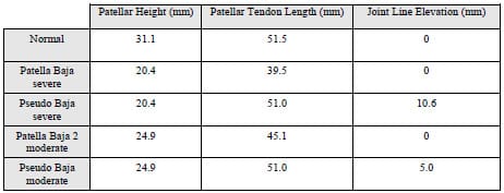
Table 5-1: Patellar height, patellar tendon length, and joint line elevation values were computed for each experimental condition.
Each dynamic squatting trial consisted of mechanical knee extension starting from 63º flexion with a 9.1 kg downward axial load applied proximal to the hip joint center using weights. The movement speed for all dynamic trials was approximately 7.5º/second. For each experimental condition listed above, three dynamic extension trials were conducted per patellar design. The ordering of experimental conditions was as follows: (1) normal, (2) pseudo patella baja severe, (3) pseudo patella baja moderate, (4) patella baja severe, and (5) patella baja moderate. Ordering was not randomized because of difficulties associated with matching patellar heights between true baja and pseudo baja conditions. With the patellar tendon length held constant, the tibial tubercle position was first moved 10.6 mm inferior to simulate joint line elevation (Figure 5-2). The tibial tubercle was then moved superiorly from this position to simulate 5.0 mm joint elevation. After returning the tibial tubercle to its original position the patellar tendon length was systematically shortened until the patellar height matched the patellar height computed for a previously collected pseudo patellar baja condition. A static trial in full extension was required to assess patellar height for every condition. This entire protocol was repeated on a second day to assess study repeatability.
5.2.4 Development of a SIMM-Based Visualization Tool
Manufacturer-supplied CAD drawings (.IGS format) were opened in Rhinoceros 3D solid modeling software (McNeel; Seattle, WA) and exported as polyhedral meshes. A custom MATLAB program converted meshes into Software for Interactive Musculoskeletal Modeling
(SIMM; Musculographics, Inc.; Santa Rosa, CA) “bone” files.
A SIMM model was developed with three independent segments connected to ground via three 6-DOF joints (Figure 5-3). These segments represented the femur, tibia, and patella segments respectively. Each segment had an additional segment connected to it by a 6-DOF joint. These “dummy” joints allowed the placement (registration) of CAD files within each local (femur, tibia, and patella) CS. The model had an additional 12 joints connected to ground representing 12 reflective markers. These joints allowed the placement of individual reflective markers to be viewed within SIMM. Markers could be interactively turned on/off within SIMM. In total the model was defined by 72 generalized coordinates.
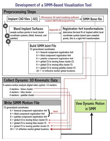
Figure 5-3: Flowchart outlining the steps required in developing a SIMM-based visualization tool.
Prior to the assembly of the mechanical knee within the testing frame, an implant registration protocol was performed (Appendix A). This registration determined three rotations and 3 translations for each component that located it in its local CS. A custom MATLAB program was written that read the motion data file (.TRC) and exported a SIMM motion file (.MOT) that contained values for all 72 generalized coordinates. From SIMM, this motion file could be opened and viewed. Following implant registration, the entire process from data collection to viewing in SIMM took less than 20 seconds (Figure 5-4).
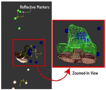
Figure 5-4: Software for Interactive Musculoskeletal Modeling (SIMM) screenshot of dynamic knee
simulator. This model allowed visualization of computer assisted design (CAD) total knee replacement
components shortly after experimentation.
5.2.5 Data Processing
All data (quadriceps tension and three-dimensional coordinates of femoral, tibial and patellar markers) were collected at 100 Hz and filtered using a low-pass 4th order Butterworth filter with a 10 Hz cutoff frequency prior to processing. Filtering was accomplished using the “filtfilt” and “butter” utilities provided within the Signal Processing Toolbox from MATLAB.
A local CS was computed for each four-marker cluster with its origin at the centroid of marker locations. A static trial was used to compute all three local CSs. Anatomical CS for the tibia and femur were computed from anatomical landmarks as has been previously explained (Grood and Suntay, 1983). An established anatomical CS for the patella has yet to be established, but an adaptation of the method proposed by Grood and Suntay (1993) to describe patellar motions has been recommended (Katchburian et al., 2003) The y-axis of an anatomical CS for the patellar implant was determined from the CAD representation of the insert and the xaxis was identical to the femoral flexion-extension axis. The 4×4 transformation matrices from the local CSs to their respective anatomical CS were fixed. For all patellar rotations and displacements, the attitude and position of a normally positioned patella in full extension was used as a baseline for all other measurements. A least-squares method based on singular value decomposition (Challis, 1995) was used to compute the 4×4 transformation from global CS to each local CS for each frame of data. A least squares approach was utilized to take advantage of the redundant fourth marker in each cluster. Tibiofemoral and patellofemoral kinematics were subsequently computed and joint angles decomposed using an Euler ZYX decomposition (1986).
5.3 Results
All abnormal distal patellar height conditions, achieved either through patellar tendon shortening or joint line elevation, decreased quadriceps efficiency compared to normal patellar height (Table 5-2). With an anatomical patellar component, a 10.7 mm reduction in patellar height due to patellar tendon shortening (patella baja severe) required a 21% larger quadriceps tension to extend the knee from the same position. A similar percentage was computed for a symmetric patellar component. There were minimal differences (< 15 N) in peak quadriceps tension required across all patellar height conditions between patellar designs. A 12% reduction in patellar tendon length (patella baja moderate), approximately equivalent to a 6 mm reduction of patellar height, increased peak quadriceps tension by over 7% for both patellar inserts designs. The angle at which peak quadriceps tension occurred varied by less than 1º over all test conditions.
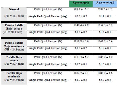
Table 5-2: Peak quadriceps tension (N) and the angle of peak tension (deg) is given for all patellar
height conditions and both patellar designs.
Subtle differences were noted between the required peak quadriceps force between patellar tendon shortening (patella baja) and joint line elevation (pseudo patella baja) conditions. For both patellar designs, patella baja conditions required more (23.3-30.0 N) quadriceps force to extend the knee from the same position as compared to pseudo patella baja.
Patellar tracking patterns and magnitudes were altered between normal patellar height and either pseudo patellar baja or patella baja conditions. Since the direction of knee flexionextension can affect patellar motion (Katchburian et al., 2003), all patellofemoral motion will be presented from flexion to extension. For normal conditions the patella tracked medially for 7 mm from 62-40º knee flexion before tracking laterally for 2 mm from 40º flexion to full extension (Figure 5-6). This is consistent with several in vitro studies of patellar kinematics (Katchburian et al., 2003). When the patellar height was reduced to 20.4 mm, either through patellar tendon shortening or joint line elevation, the patella was laterally shifted over 7 mm when compared to normal patellar height conditions at 62º of knee flexion for both patellar implants. The patella tracked medially as the knee extended but remained more lateral than during normal conditions. For pseudo patella baja conditions, the anatomic patellar implant had approximately 4 mm more of lateral shift (Figure 5-7) and 7 mm less anterior displacement as compared to the symmetric implant (Figure 5-9).
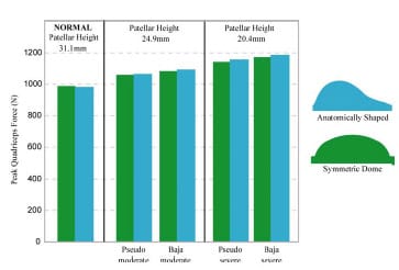
Figure 5-5: Bar graph depicting peak quadriceps tension (N) for a mechanical knee model undergoing
extension with different patellar heights.
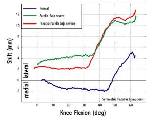
Figure 5-6: Any reduction of patellar height increased patellar lateral shift from normal conditions
for flexion angles greater than 30º. For normal conditions the patella tracked medially for 2 mm before
tra
cking laterally for 7 mm after 45º flexion.
Patellar flexion increased with knee flexion angle for all conditions and both patellar designs (Figure 5-8). For knee flexion angles 40º and greater, both patellar designs exhibited greater flexion in any reduced patellar height condition as compared to normal conditions. Patella baja conditions produced a more flexed patellar position than pseudo patella baja for the entire knee flexion range of motion. Tibial and patellar contact force calculations were unreliable and will not be reported.
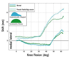
Figure 5-7: After 50° flexion the anatomical patellar component was more laterally displaced as
compared to the symmetric patellar implant.
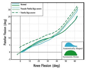
Figure 5-8: For pseudo patellar baja conditions the patellar flexion angle was greater than normal
patellar height conditions at flexion angles 45º and higher. Patellar flexion angle was greater for all
flexion angles for patella baja conditions as opposed to pseudo patella baja conditions.
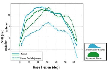
Figure 5-9: Anterior-posterior displacement of the patellar component was substantially reduced for
pseudo patella baja conditions with an anatomical patellar design.
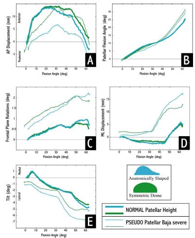
Figure 5-10: For normal patellar height, both patellar designs exhibited similar motion patterns, but
for pseudo patella baja conditions their motions differed.
5.4 Discussion
The present study investigated the differences between two mechanisms of reduced patellar height following TKR using a mechanical knee model that allowed systematic control of patellar tendon length and joint line elevation. The patella functions as a spacer increasing the moment arm of the quadriceps muscle group and effectively improving knee extension capability (Kaufer, 1971). The current study showed that for any reduction of patellar height, either through patellar tendon shortening or joint line elevation, the tension within the quadriceps would be increased thus making knee extension from 60º flexion more difficult. This result could have clinical ramifications as 50-60º knee flexion is typically reported during stair climbing (D’Lima et al., 2001). As a result of the increased quadriceps tension required to extend the knee, higher forces distributed across the patellofemoral joint could accelerate polyethylene wear and thus jeopardize implant longevity.
Patellar component design had little effect on the extensor mechanism efficiency for either patellar baja or pseudo patellar baja conditions. Since both patellar geometries tested within this study had the same thickness, it is not surprising that negligible differences were noted between their affect on the extensor mechanism. Congruity between the patellar geometry and trochlear groove has implications on stability and loading of the medial and lateral patellar facets (Walker, 2001). Increased congruence will increase contact area, lower contact pressure, and prevent accelerated polyethylene wear. Although patellar design did not alter patellofemoral mechanics in the present study, patellar tracking was dependent on design. For a normal patellar height, the designs displayed nearly identical motions but as patellar height was reduced, their tracking and rotations differed (Figure 5-10). The most notable differences were increased lateral tracking (>3 mm) and decreased anterior translation (>5 mm) of the anatomical design. It would appear that because anatomical patellar designs have an increased lateral facet size, they are more prone to track laterally when the patella is not properly positioned in the sagittal plane. This finding agreed with a study by Malo and Vince (2003) that stated anatomic patellar designs have a greater capacity to track poorly when they are positioned poorly, indicating that a symmetric implant may be more forgiving to surgical error. Lateral tracking can also accelerate polyethylene wear as joint contact forces are concentrated at the edge of the implant (Stulberg et al., 1988).
Entrapment of the patella within the femoral trochlear groove has been cited as a potential problem of a reduced patellar height and an associated quadriceps weakness (Paulos et al., 1987; Noyes et al., 1991). The results of the present study supported this finding. Both mechanisms of patellar height reduction produced an increased patellar flexion angle for knee flexion angles greater than 40°. Flexion of the patellar about a transverse axis rotates the distal edge of the implant towards the femoral component. Patella baja conditions increased patellar flexion throughout the entire knee extension range of motion. As a result of this flexed position, the contact location on the patella can be expected to move distally. This point can be verified through a simple planar geometrical model (Figure 5-11). Due to an increased angle between the patellar tendon and the long axis of the tibia, patella baja conditions create patellar flexion moments. Although the patellar tendon does not appear to elevate the risk of entrapment more so than joint line elevation, it would appear that patellar tendon shortening may influence contact area by flexing the patella throughout the entire knee ROM.
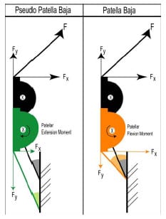
Figure 5-11: Due the angle of the patellar tendon with respect to the long axis of the tibia, a
patella baja condition creates a patellar flexion moment. The black patella
represents normal patellar height.
A number of limitations should be noted regarding the mechanical TKR model used within this study. It is well accepted that patellar tracking is the combined effect of design, tightness of the patellar retinaculum, rotation of femoral and tibial components, and quadriceps angle. (Wright, 2000; Malo and Vince, 2003). The present model did not attempt to model the patellar retinaculum, although its presence can be expected to influence patellar motion. A single line of action approximated the quadriceps muscle group, but anatomically the quadriceps attaches along the entire proximal border complicating the forces acting upon it. Patellar tendon shortening was accomplished by physically altering the amount of webbing between the patella and tibial tubercle. Physiological tendon shortening, secondary to an injury mechanism, occurs through the formation of fibrous connective tissue and reorganization of tissue structure. The resulting shorter tendon could have different viscoelastic properties compared to those of t
he original tendon. The present model did not alter tendon properties from the normal to shortened condition. Only 60° of knee flexion could be accommodated by the dynamic knee simulator used within this study, although more profound differences may have been exhibited between patellar tendon shortening and joint line elevation if higher degrees of flexion were possible.
A secondary objective of this study was the development of a computational method to determine implant contact areas from measured kinematic data. Although this tool would have added considerably to the findings of this study, the method was not able to reliably determine implant contact areas. Appendix D has a complete description of the techniques that were attempted and commentary on potential reasons for failure. A useful subsidiary of this project was the development of a SIMM-based visualization tool (Section 5.2.4). This visualization tool provides prompt feedback during experimental data collection, and it allows researchers the ability to replay experimental trials after they have been collected. For instance, the differences noted in the kinematic data collected in this study (Figure 5-10: A-E) could be visualized within this tool for a deeper appreciation of their meaning. This tool could also be used during cadaver TKR experimentation. If implant registration occurred after implantation and prior to the medial incision being sutured back together, then it would be possible to visualize implant motion within the SIMM tool without being able to actually see the physical implants in the cadaver knee.
The results of the present study suggest that TKR patient function may be significantly impaired from a reduction of patellar height. Reduced patellar height will require increased quadriceps force in TKR patients performing such activities as stair climbing or rising from a chair. This is a significant finding because studies have shown that TKR patients have less muscular strength then age-matched contemporaries one year post-operatively (Mizner et al., 2005). Furthermore, the results of the present study suggest that patellar implant design may influence patellofemoral motions (i.e. lateral tracking and patellar flexion) without substantially altering the extensor mechanism. A symmetric patellar implant was more resistant to lateral tracking when the patella height was reduced through either mechanism. Future studies should investigate contact patterns of symmetric and anatomical patellar implants for patellar tendon shortening and joint line elevation conditions. A computational modeling approach may be best suited to answer this research question, since measuring in vitro implant contact patterns and experimental simulation of tendon shortening is extremely difficult.
CHAPTER 6 – BIOMECHANICAL ASSESSMENT OF MICROMOTION IN CEMENTLESS FEMORAL COMPONENTS IN TOTAL KNEE REPLACEMENT
6.1 Introduction
Clinical success of press-fit cementless femoral components in total knee replacement (TKR) is predicated upon adequate osseointegration (bony ingrowth or apposition) (Sumner et al., 2001). Necessary conditions for bony ingrowth include (1) minimal interface gap between component and underlying bone and (2) initial component stability (minimal micromotion). Implant design may also be a factor influencing component fixation (Ducheyne et al., 1977). Numerous studies have examined the role of design with regard to rigid body motion in both total hip and knee replacement (Kraemer et al., 1995), but few biomechanical studies have attempted to measure the micromotion of cementless femoral components in TKR.
Initial component fit to the underlying bone has the potential to influence tissue migration into porous-coated components. Dalton et al. (1995) showed that interface gaps greater than 1 mm significantly disrupted bony ingrowth. Cementless fixation of knee components depends upon effective surgical technique to attain the required fit between component and bone (Fanning et al., 1996). Inaccuracies in femoral cuts have been shown to create interface gaps in excess of 0.5 mm, potentially compromising bony ingrowth into porous-coated components (Lennox et al., 1988).
Excessive micromotion between the component and the surrounding host bone has been shown to prevent adequate ingrowth. In a canine model, Pilliar et al. (1986) demonstrated that bony ingrowth occurs in the presence of micromotion less than 28 µm, but motions greater than 150 µm resulted in fibrous connective tissue between component and underlying bone. In a study of retrieved cemented femoral components in total hip replacement, as much as 40 µm of axial motion allowed osteointegration with limited intervention by fibrous tissues (Maloney et al., 1989). A recent study on cementless tibial inserts reported bony ingrowth occurred only in regions of minimal micromotion, although it was not specified what threshold of motion produced the most ingrowth (Fuiko et al., 2003). Although many studies have investigated the micromotion and migration patterns of tibial inserts (Ryd, 1986; Ryd et al., 1988; Andriachi et al., 1989; Ryd et al., 1993; Kraemer et al., 1995), few have investigated the micromotion patterns of cementless femoral components (Nilsson et al., 1990; Wackerhagen et al., 1992; Nilsson et al., 1995).
Numerous clinical studies have investigated the fixation success of cementless TKR designs (Hefzy, 1988; Gacon et al., 1995; Kim et al., 1995; Fanning et al., 1996; Heftzy and Cooke, 1996; Berger et al., 2001; Piazza and Delp, 2001). Conflicting reports have been published regarding the initial effectiveness of a cementless approach. Moran et al. (1991) reported that 19% of cementless tibial inserts required revision within 5 years of implantation. In contrast, Joseph and Kaufman (1990) reported good to excellent results in 91% of 42 cementless procedures at a mean follow-up of 3.6 years. Failure of cementless TKR was most often associated with loosening of the patellar or tibial components.
Loosening of the femoral component has seldom been indicated as a failure mode in cementless TKR (Nilsson et al., 1995). In fact, several short-term follow-up studies have indicated that cementless femoral fixation rates were comparable to cemented fixation (Wright et al., 1990; Rosenberg et al., 1990; Collins et al., 1991; Baldwin et al., 1996; Fanning et al., 1996). In an 11 year follow-up study, Berger et al. (2001) reported no femoral fixation problems in 131 cementless TKR procedures and classified cementless femoral fixation as “excellent”. Despite these encouraging clinical outcomes, cementless femoral components that were revised for reasons other than loosening have displayed bony ingrowth rates as low as those observed for tibial components (Cook et al., 1989).
Since loosening of cementless femoral components is uncommon, investigation of femoral component micromotions has been limited. Nilsson et al. (1995) conducted an in vivo roentgen stereophotogrammetric analysis (RSA) study investigating the micromotion and migration (movement over time) of cemented and cementless Miller-Galante I (Zimmer; Warsaw, IN) femoral components. The migratory results for both fixation types were similar, with the main component of migration occurring as rotations about the transverse (flexionextension) axis. Despite having clinical success with regard to fixation, both translational and rotational micromotions of the cementless femoral component were of the same magnitude as those reported previously for tibial components. The authors speculated that, “the shape [design] of the femoral component may be more efficient in preventing progression of the micromotion into clinical loosening”. An in vitro biomechanical study by Wackerhagen et al. (1992) found that anterior-posterior micromotions at the anterior flange of cementless femoral components were more than twice those of cemented components. The investigators reported th
at “anterior rocking” about a transverse axis of the component relative to the underlying bone occurred with or without the presence of cement.
Although cementless femoral component loosening does not appear to be a problem currently, recent modifications to femoral component designs, intended to maximize flexion, could alter micromotion patterns. “High-flex[ion]” knees require an additional 2-4 mm of posterior condyle bone resection (Ranawat, 2003). This alteration of posterior femoral cuts may increase the likelihood of anterior rocking. Presently the effect on micromotion to the angle of femoral bone cuts is unknown.
The purpose of the present study was to investigate micromotion patterns occurring in two cementless femoral component designs. A dynamic mechanical knee simulator was used to apply physiological forces to the knee components while movements between the femoral component and a bone substitute were measured. Two cruciate retaining (CR) total knee designs, requiring different femoral bone cuts, were tested. Micromotions at each bone cut plane were estimated.
6.2 Methodolog
6.2.1 Total Knee Designs Two medium-sized cementless posterior cruciate ligament retaining total knee designs (PCR) were tested: the Duracon Cruciate Retaining Total Knee (Stryker Orthopaedics; Mahwah, NJ) and the Triathlon Cruciate Retaining Total Knee (Stryker Orthopaedics; Mahwah, NJ). The femoral components of these designs differ in their condyle curvatures and in the required femoral bone cuts. Implantation of the Triathlon design requires a 7º anterior femoral cut compared to a 5º cut required for the Duracon design (Figure 6-1). This 7º anterior flange design provides surgeons the advantage of downsizing the femoral component during implantation without the risk of notching the anterior cortex. The designs were similar with regards to both tibial and patellar geometries.
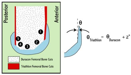
Figure 6-1: The Triathlon CR design (Stryker Orthopaedics; Mahwah, NJ) required a 2º greater
femoral anterior cut than the Duracon CR design (Stryker Orthopaedics; Mahwah, NJ). Cut plane designations
are represented by a black circle with number.
6.2.2 Experimental Apparatus
To assess femoral component micromotion patterns under physiological loading conditions, a mechanical PCR model was employed (Figure 6-2). The following anatomical features were considered in the design of the simulator: (1) quadriceps angle, (2) tibial tubercle location, (3) patellar height in sagittal plane, (4) femoral and tibial segment lengths, (4) location of posterior cruciate ligament (PCL) insertions, (5) hamstring insertions, (6) and quadriceps force direction. Semi-rigid polyurethane foam (Last-A-Foam FR-6712; General Plastics Manufacturing Company; Tacoma, WA) was used to substitute for the surrounding femoral bone (both cancellous and cortical). This approach has been taken in previous biomechanical studies of micromotion at other joints (Bai et al., 2000; Gortz et al., 2002; Mohr et al., 2004). The ultimate stress and elastic modulus of the foam were 3.4 MPa and 106.1 MPa, respectively. Li and Aspden (1997) reported mean values of 2.5 MPa (range: 0.4-5.5 MPa) and 247 MPa (range: 80-410 MPa) for human distal femoral epiphysis bone samples from patients with osteoporosis (OP). Femoral bone cuts were made in accordance with a least material condition (LMC), that approximated the maximum surgical error expected (i.e., removing the most bone) with use each design’s instrumentation system. This LMC approach was adopted to simulate a “worst-case” set of bone cuts.
Nylon webbing (width = 2.54 cm) was used to represent the patellar ligament and quadriceps tendon (QT) while climbing rope (dia = 0.6 cm) (Sterling Rope Company; Scarborough, ME) simulated the retained PCL. Uniaxial tensile testing was performed in a servohydraulic materials testing machine (Instron; Eden Prairie, MN) to ensure that the webbing and rope had similar stiffness values to those reported in literature. An oblique hole was drilled through each foam block that simulated the physiological PCL line of action based upon literature references (Racanelli and Drez, 1994; Morgan et al., 1997; Wu et al., 1998; Harner et al., 1999; Liau et al., 2002). More specific details are provided in section 6.2.4 and Appendix C.
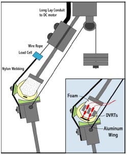
Figure 6-2: A mechanical total knee replacement posterior cruciate ligament retaining simulator was
utilized to assess micromotion between the femoral component and surrounding foam (bone substitute). The
DVRTs were rigidly attached to the foam while the aluminum wing was rigidly fixated to the femoral component
via the extraction slot.
A custom knee rig (Cain, 2002) was modified to simulate both gait and squatting movements. The rig was designed with ball-and-socket joint representations for the hip and ankle and with the hip joint center constrained to a proximal position directly above the ankle joint center. Loads simulating body weight could be systematically adjusted with the addition of weights placed atop the hip. The quadriceps line of action represented that of the vastus intermedius muscle and rectus femoris groups as these muscles have similar line of actions and carry a substantial fraction of quadriceps load (Zhang et al., 2003). A brush-driven DC motor (Runyes Corp.;, China) provided actuation of the quadriceps as the speed of quadriceps tendon displacement could be controlled via input voltage. Medial and lateral hamstring contributions were simulated by hanging a 9 kg weight from two 0.4 cm diameter steel cables that were routed around a pulley simulating the ischial tuberoisty. These cables were attached to the tibial segment in locations approximating the insertions of the semimembranosus/semitendinosus (medial) and biceps femoris (lateral) muscle groups respectively (Figure 6-2). A swivel connection at the tibial insertions allowed the line of action to remain physiologic throughout knee flexion.
Three subminiature gauging differential variable reluctance transducers (DVRTs) (MicroStrain Inc.; Burlington, VT) were used to measure displacement between the foam block and femoral component. These sensors have a manufacturer-reported resolution of 2 μm. For DVRT mounting to the foam block, two individual aluminum plates were attached to the medial and lateral sides of each block using a commercially available cyanoacrylate adhesive (LockTite SuperGlue; Avon, OH). The plates were attached to each block using the corner of cut planes #3 and #4 and the inferior edge as references. This allowed nearly identical plate fixation on each block with each plate nearly flush with the foam’s inferior edge. Three divot holes machined into identical locations on the lateral plates were used to establish a block-fixed coordinate system (CS) later in the protocol. The medial DVRT was permanently mounted to an aluminum plate using a plastic collar while the two lateral DVRTs were similarly mounted to another plate. These mounting DVRT plates could then be bolted to the plates that were glued on each foam block (Figure 6-3). This arrangement ensured that each DVRT was aligned w
ith the vertical axis of each foam block. Each DVRT plunger contacted an aluminum “wing” that was rigidly attached to the femoral component. Rigid attachment of both medial and lateral wings was accomplished by press-fitting and gluing a pegged insert into the extraction slots of the components.
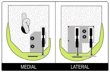
Figure 6-3: Schematic illustrating the mounting of DVRTs on foam block. Aluminum mounting plates
were glued in the same location on each block. The DVRT mounting plate could then be bolted to
each mounting plate, securing the DVRT to the foam block. Divot holes (red dots) were machined
into the lateral plate to establish a block-fixed coordinate system. A knot was tied into the
climbing rope used to simulate the posterior cruciate ligament.
6.2.3 Mathematical Computation of Micromotion
Determination of micromotion of the femoral segment relative to the surrounding foam was calculated using a rigid body analysis (Gilbert et al., 1993). This approach assumed that the foam block was rigid, and the potential for error due to this assumption is discussed in the following section. The three DVRT permitted measurement of the following three DOF between the segments: superior-inferior (SI) translation, flexion-extension (FE) rotations, and varusvalgus (VV) rotations.
A Microscribe 3DX digitizer (Immersion Corp.; Urbana, IL) was used to digitize three divots in the mounting plate glued on each foam block with a precision of 0.4 mm. A blockfixed coordinate system (CS) could thus be established. Low-scale Fuji Prescale film (Sensor Products Inc.; East Hanover, NJ) placed between each DVRT gauge and the aluminum wings extending from the femoral component allowed the three contact points to be accurately marked. The three contact points were then digitized within the block-fixed CS, and thus the femoral component CS could be located within the block-fixed CS (Figure 6-4). Following digitization of the contact points, 5-10 points were systematically sampled from each bony cut plane in block-fixed CS and subsequently converted to the femoral component CS.
It was assumed that DVRT contact points translated only along the block-fixed CS y-axis throughout the trials. Due to the separation of contact points the potential magnitude of error for this assumption was investigated and found to be less than 0.01 µm (Figure 6-4). Therefore, for each frame of collected DVRT data, the block-fixed CS y-coordinates of each contact point were displaced and a new femoral component CS could be determined. Subsequently the new blockfixed coordinates of the digitized cut plane points could be computed and compared to their respective initial values from Equations 6.1-6.3:

where D is an n x 3 matrix of digitized points from cut plane j and Tg-l is the 4×4 rigid transformation from block-fixed CS to femoral component CS. Micromotion, μM, was then computed for each data frame and for each cut plane by selecting the maximum norm of the displacement of any digitized point from that cut plane. Maximum micromotion for the entire trial for each cut plane equaled the largest micromotion value computed across all frames of data. The component displacements of cut plane points were analyzed to assess the nature of motion between the two segments.
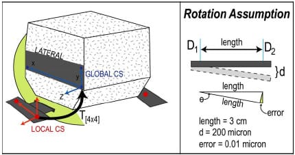
Figure 6-4: Schematic illustrating the location of global and local coordinate systems (CS) (left).
The red dots indicate the contact points of DVRTs with aluminum wings. Since each DVRT was aligned
with the global y-axis, for each frame of data a new y-coordinate could be determined for each
contact point and subsequently a new 4×4 transformation from local CS to global CS.
This is based upon the rotation assumption illustrated (right).
6.2.4 Experimental Method
An abbreviated protocol is presented here; a more detailed protocol has been provided in Appendix D. Eight blocks per knee design were machined to LMC standards and aluminum mounting blocks were glued to medial and lateral sides. All femoral components were seated on the foam blocks by the same experimenter with two rubber mallet blows.
Assembly of the mechanical knee model required tensioning of the PCL at 30º flexion with ~270 N force as measured by the use of a spring scale. A ball-bearing cleat (Harken; Pewaukee, WI) was utilized to fix the PCL on the tibial segment and a knot just outside the medial exit hole on block provided a rigid fixation on femoral segment. The required force to extend the knee was measured using a uniaxial load cell (Omega Inc.; Stamford, CT) in series with the QT while a digital motion analysis system (Motion Analysis System; Santa Rosa, CA) was used to track tibial, femoral, and patellar motions respectively. Each segment (femur, tibia, and patella) had a 4-marker cluster rigidly attached using screws. Patellar markers (dia = 1.0 cm) were slightly smaller than tibial and femoral markers (dia = 1.5 cm) to avoid convergence of markers during each trial. A four camera arrangement was utilized to insure that at least three cameras had a clear view of each marker. Proper positioning of cameras prior to data collection insured this criteria was always met. Cameras were routinely calibrated with an error residual of 0.12 ± 0.05mm. This indicated that the motion analysis system was capable of determining marker centroid position within this tolerance. A three-marker (diameter = 2.54 cm) digitizing wand was used to approximate the position of bony landmarks used for establishing a clinically relevant knee joint coordinate system (CS) (Grood and Suntay, 1983). To determine the sagittal patellar height of the patella three points were located from the lowest portion of the dished tibial insert and one point from the most inferior position of the patellar implant. The equation of a plane was computed from the three tibial points and the perpendicular distance of the patellar implant to the tibial plane computed. The patella was systematically altered to accomplish a sagittal height of 35 mm as reported in literature (Norman et al., 1983).
After the mechanical knee assembly, DVRTs were attached to foam mounting blocks. Five squat preconditioning trials were completed to ensure proper seating of the femoral component. Following preconditioning all DVRTs were zeroed. Three movement simulations (squat, chair rise, gait) were tested per foam block. During squatting simulations the axial load was set at ~16 kg and each trial began from ~60º knee flexion. For chair rise simulations, static poses were collected at full extension and at ~95º knee flexion. Quadriceps tension was monitored and matched between trials. Dynamic knee extension was not possible because the required quadri
ceps force exceeded the capabilities of the brush-drive DC motor. For gait simulations, the axial load was increased to ~63 kg and each trial began from ~25º knee flexion. Rather than average trials across each simulation, which has the potential to reduce peak values, a representative trial was used to represent each set of five trials. A Microscribe 3DX digitizer was used to locate DVRT contact points and points along each cut plane as described in the previous section. After the completion of the eighth block the knee system design was changed without altering the anatomical alignment of the knee.
A final control foam block was tested to ascertain the effect of local foam deformations on the measurement of micromotion. A foam block was glued to a femoral component using a commercially available adhesive (Gorilla Glue; Cincinnati, OH) to prevent rigid body motions between the two segments. These results were then analyzed to assess the effect of deformation on the proposed rigid body assumption.
All data (DVRT displacements, QT force, and three-dimensional kinematics of the femoral, tibial and patellar segment) were collected at 100 Hz and low pass filtered with a 10 Hz cutoff frequency prior to processing. The movement speed for all trials was approximately 7.5º/second. Custom MATLAB (Mathworks; Natick, MA) programs were written to compute knee joint angles and maximum micromotion at each cut plane. DVRT recordings at peak quadriceps force were used as a baseline to eliminate the potential effect of thermal drift within position sensors. Two-way analyses of variance (ANOVAs) were run with factors of TKR design (Duracon and Triathlon) and cut plane (1-5) for squat, chair rise, and gait simulations. Tukey pair-wise comparisons were performed following each ANOVA to identify significant differences in maximum micromotion. A statistical significant p-value was set at the alpha level 0.05.
6.3 Results
6.3.1 Repeatability of Measures
Both DVRT recordings and quadriceps force were found to be repeatable between trials of either gait or squatting. Within each foam block, DVRT recordings varied less than 20 μm for all trials of a given simulation type. Across foam blocks, representative trials showed good agreement (Figure 6-5). The magnitude of peak quadriceps force computed across five squat or gait trials were repeatable within 20 N respectively. Peak quadriceps force was reduced from squatting to gait simulations and mean peak quadriceps force differences between knee designs were less than 100 N (Table 6-1). Since the precise mounting of DVRT sensors was required for the analysis, the comparison of the global coordinates of DVRT contact points with the aluminum wings was computed for both Duracon and Triathlon knee systems. For both knee designs the location of all three contact points was found to vary by less than 1.4 mm (Table 6-2).
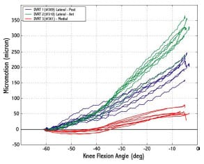
Figure 6-5: Differential variable reluctance transducer recordings were repeatable between trials.
All recordings start from 0 because the reading at peak quadriceps force was used as a baseline.
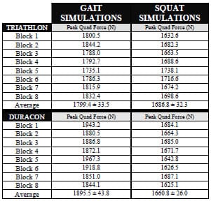
Table 6-1: Mean peak quadriceps force and the angle at peak force were averaged across five
gait and five squat trials for every foam block. Total mean values standard deviations
were then computed across knee design for both simulations.
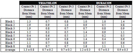
Table 6-2: Mean location was computed for all three contact points using data from eight
foam blocks. The distance from this mean location was computed for each block and presented
in the table. All contact points were repeatable located within an average of less than 1mm.
6.3.2 Micromotions
For gait simulations, both Triathlon and Duracon experienced similar micromotion patterns at all cut planes (Figure 6-6). Mean maximum micromotion displacements were all less than 150 μm, with the exception of the anterior cut plane of Triathlon where the mean was 154.5 μm. No statistical significance (p > 0.05) was found between TKR design at any cut plane. Standard deviations were below 50 μm for all cut planes.
For squat simulations, Triathlon mean maximum micromotions were on average 47% less than mean values computed for Duracon, and statistical significant differences were found at every cut plane (P < 0.01) (Figure 6-7). For the Triathlon knee system, all mean maximum micromotion values reported were less than 175 μm. The largest micromotions (> 250 μm), for the Duracon knee design, were experienced on posterior cuts #1 and #3, both lateral cuts. For chair rise simulations, no statistical significant differences were computed between the TKR knee systems at any cut plane (Figure 6-8). For both TKR knee designs the largest micromotions were noted for posterior cuts #1 and #3 (> 175 μm). On average, the micromotions were greater than experienced during gait simulations but comparable to the squat simulations.
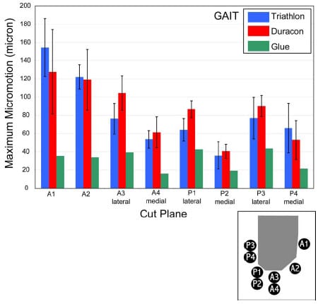
Figure 6-6: Mean maximum micromotions were not statistically significant between knee designs
at any flexion angle for gait simulations. More variability was noticed within
Triathlon results as opposed to Duracon.
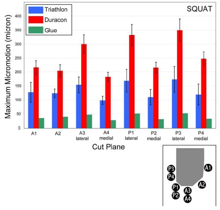
Figure 6-7: Mean maximum micromotions for a squatting simulation were significantly larger for
Duracon as compared to Triathlon. Statistical significance was found between the designs
at every cut plane (p < 0.01).
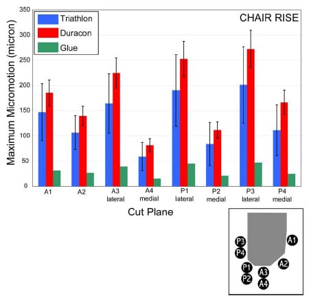
Figure 6-8: Mean maximum micromotions for a chair rise simulation were similar for both knee designs.
6.3.3 Rigid Foam Assumption
In order to investigate the rigid body assumption used in this study to calculate micromotion, experimental trials were collected from a previously tested foam block glued to a Triathlon femoral component component. Gluing of the foam block to the Triathlon knee design reduced micromotions by 57%, 71%, and 76% for gait, squat and chair rise simulations respectively (Figure 6-6, Figure 6-7, Figure 6-8; green bar). Standard deviation bars were not displayed because only one foam block w
as tested under this condition. All micromotions were less than 50 μm when components were glued to the foam blocks.
6.4 Discussion
Micromotion patterns were computed for two cementless femoral component designs subjected to simulated physiologic loading. The present study adapted a previously published rigid body analysis technique for determining motion between a press-fit femoral component and the underlying foam through the use of displacement sensors (Gilbert et al., 1993). One of the major differences between Duracon CR and Triathlon CR knee systems is a 2º angular difference of the femoral anterior cut (Figure 6-1). Since it has been speculated that micromotion patterns in femoral components occur primarily about the flexion-extension axis (King and Scott, 1985), this design alteration could potentially increase the possibility of rotary micromotion in the Triathlon CR design. The results of the present study found no statistical differences between the magnitude of micromotion at any cut plane between Duracon CR and Triathlon CR for gait and chair rise simulations (all P > 0.05). However, Triathlon CR design was found to provide significantly greater resistance to micromotions as compared to the Duracon CR design for squat simulations. Although it is difficult to determine the mechanism for this reduction of micromotion, it is speculated that the increased 2º anterior cut altered the resultant patellofemoral contact force direction.
King and Scott (1985) speculated that the posterior bone-femoral component contact interface was critical for femoral component fixation. Making accurate cuts on the posterior condyles may be more difficult than the anterior cuts because of a lack of visual exposure. This could result in larger interface gaps on the posterior cuts. As a result of these gaps at high flexion angles, a cementless femoral component could display “anterior rocking” relative to the underlying bone (Wackerhagen et al., 1992). The present study prepared foam blocks with a LMC approach, indicating a worst-case scenario for all cut planes. Although the overall fit at every cut plane was diminished in the present study, maximum micromotions were observed at posterior cuts #1 and #3 for both squat and chair rise simulations. Since only 25º of knee flexion was simulated for gait trials, it is not surprising that the largest micromotion patterns were found for the anterior cut planes. These findings indicate that micromotion patterns are sensitive to movement simulations (i.e. knee flexion and joint loading). Although further investigation is warranted before making clinical recommendations, the findings of this study suggest that squatting or chair rise movements increase the potential for femoral component micromotion on the posterior bony cuts and this may have implications with initial component stability.
In order to calculate micromotions a number of assumptions were required. Andriacchi et al. (1989), using a combined experimental and finite element model (FEM), determined that substantial tibial bone deformation occurred relative to the measured rigid body motion between insert and host bone because of the large elastic modulus differential between bone and tibial component. In contrast, an experimental study of total hip replacement components by Gilbert et al. (1993) reported that bone deformation contributed only 3-15 μm to the total micromotion measurements. Ryd (1986) used a finite element (FE) analysis to show that magnitudes of tibial bone displacement were an order of magnitude lower than displacement measured using RSA. In the present study a rigid body analysis was utilized to measure motion between the femoral component and foam, although local foam deformations occurred during testing. Deformation occurred because of the large elastic modulus differential between cobalt-chrome (femoral component) and the foam used within this study. Ideally, trials conducted with the foam glued to the femoral component would have produced zero displacement indicating that deformation was not occurring. Although measured displacements from the glued trials were sizable (< 50 μm), these errors would only cause overestimations of the true micromotion magnitudes. Due to the complicated loading environment, a FE analysis would be required to compute the expected foam deformation, but this type of computational analysis was beyond the scope of this study. As a result it is difficult to discern that exact magnitude that micromotions are overestimated, but it is expected that it is more than the 3-15 μm range reported by Gilbert et al. (1993).
The mechanical knee simulator provided a novel experimental design to apply quasiphysiological loads to the TKR joint in a controlled environment. The repeatability of the required maximum quadriceps force to extend the knee and the timing of such force verified the reproducibility of the generated kinetics. The magnitude of quadriceps forces far exceeded values (> 500 N) reported for similar knee extension simulations using cadaver specimens (D’Lima et al., 2001; Zavatsky et al., 2004; Browne et al., 2005). Although the present study can be used in a heuristic sense as a comparative analysis of two TKR designs, caution should be taken in attempting to interpret results in a clinical framework. Since quadriceps force was found to be sensitive to certain parameters (i.e. internal-external rotation of the femur), further investigation needs to be conducted before clinical interpretations can follow.
The methods of the present study could be improved to gain a more functional understanding of the role of femoral component design on micromotion patterns. The foam selected for this study displayed a smaller elastic modulus than the mean literature value given for OP bone (Li and Aspden, 1997). Since it has been shown that foam deformation will contribute to errors in rigid body motion calculations, selection of stiffer foam should reduce the magnitudes of these errors and give more realistic motion predictions. Canine models have shown that the surrounding cortical ring provides transverse constraint against micromotion in tibial components (Berzins et al., 1994). The foam used in the present study lacked a cortical ring analogue, although it is unclear what effect this omission had on the present results. The present study was limited by the use of three DVRTs and, as a result, only three DOFs could be measured. Because the aluminum wing extending from the femoral segment was parallel with the most inferior bony cut, it was possible for medial-lateral translations, anterior-posterior translations and internal-external rotations to go undetected by the sensors. Both of these femoral designs contain two tapered pegs extending into the foam, and it was speculated that both translations would be largely prevented. A more thorough and complete understanding of the actual micromotion could be computed by the addition of three additional sensors. Nilsson et al. (1995) found that internal-external rotations were similar to flexion-extension rotations in an in vivo RSA study of uncemented femoral TKR components. Although the mechanical knee simulations allowed for accurate control of certain design variables (i.e., bone cut accuracy), cadaver testing could corroborate the findings of this study.
In conclusion, a rigid body analysis was used to compute magnitudes of micromotion at eight femoral cut planes in two TKR designs. Although the TKR designs differed in regards to their required femoral bony cuts, they produced similar micromotion magnitudes for both gait and chair rise. Triathlon CR was more resistant to micromotions during squat simulations. Although deformations within the foam exaggerated computed micromotions, these overestimations would be consistent across all foam blocks. Micromotion of the femoral component appears to be more complicated than just a cyclic rocking about a transverse axis as has been previously re
ported (King and Scott, 1985; Wackerhagen et al., 1992), and in agreement with the findings of Nilsson et al. (1995) appears to be a combination of multi-planar movement. The press-fit cementless femoral components tested were equally capable of resisting motion relative to the underlying foam when subjected to physiological forces during gait and chair rise simulations. Increasing the angle of the anterior cut plane by 2º may contribute to a significant reduction of the measured micromotions at all cut planes for a squat simulation.
6.5 Acknowledgments
This work was supported by Stryker Orthopaedics (Mahwah, NJ).
CHAPTER 7 – CONCLUSIONS
7.1 Summary
Four independent studies relating to total knee replacement (TKR) motion comprised this dissertation. Although these studies analyzed TKR motion from different perspectives, they all involved investigation of factors that influence joint function and stability following TKR. Several novel computational and experimental research methodologies were developed in the course of completing this dissertation.
A dynamic computer simulation of a range of constraint laxity test for TKR implants was developed and tested against experimental data (Chapter 3). Conformity of the tibial insert relative to the femoral component is known to affect post-operative laxity throughout the range of knee motion. Numerous implant designs are currently available because no consensus has been reached regarding an optimal design (Sathasivam and Walker, 1999). A range of constraint test is a standard assessment tool of knee implants in the orthopedic industry. Presently there remains controversy regarding the exact protocol that should be implemented (Haider and Walker, 2005). Tests performed using the model developed for this dissertation revealed that if secondary motions are permitted during a range of constraint test, then both anterior-posterior and internal-external rotational constraint will be reduced. Model outputs compared favorably to experimental constraint values only when artifacts in the laxity testing simulator (deflection of vertical testing arm) were represented. The ASTM protocol was developed to “provide comparable data from individual investigators” (ASTM, 2005), but the results of this thesis indicate that computational modeling provides certain advantages over experimental testing.
The computational model of the range of constraint test was augmented with a posterior cruciate ligament (PCL) to assess anterior-posterior (AP) stability in TKR designs that retain the PCL (Chapter 4). AP stability following TKR in which the PCL is retained (PCR) is derived from implant congruity and PCL function. Even with precise surgical technique during TKR, PCL function may be altered following surgery. The presence of a tight PCL will restrict AP laxity and limit maximum flexion. Two treatment options for a tight PCL have been described: (1) increased sloping of the posterior tibia, and (2) partial release of the anterolateral bundle of the PCL. The present model simulated both of these treatments in a variety of magnitudes to assess their individual and combined effect on increasing AP laxity. Although both treatments were effective at increasing anterior laxity, only partial PCL release was effective at increasing overall AP laxity. In simulations of increased tibial slope, the neutral (resting) point between the femoral component and tibial insert was more posteriorly located and thus reduced posterior laxity. Clinically, this may have implications for posterior insert polyethylene wear.
A dynamic mechanical knee simulator was developed to simulate squatting in a posterior-substituting TKR (Chapter 5). This mechanical model was used to investigate differences in two methods of acquiring a distally-located patella following TKR: (1) patellar tendon shrinkage, and (2) joint line elevation. Patellofemoral complications are the leading causes of complications following TKR. The patella increases the moment arm of the quadriceps as it acts like a lever during knee flexion (Grelsamer and Weinstein, 2001). Alterations to patellar height have been shown to alter patellar contact patterns and influence the extensor mechanism. Both methods of reducing the patellar height substantially increased the quadriceps force required to extend the knee. Patellar tendon shrinkage caused the patella to remain flexed throughout knee flexion-extension increasing the chances of patellar entrapment in the trochlear groove. Although both symmetric and anatomic patellar designs produced similar effects on the required quadriceps force, the anatomic design tracked more laterally and was displaced less anteriorly compared to the symmetric design. Although an anatomic patellar component was designed for increased congruence with the trochlear groove, this model suggests that if the patellar height is reduced an anatomic implant is more prone to maltracking problems compared to a symmetric implant.
This dynamic mechanical TKR model was augmented to investigate femoral component micromotion in a cementless PCR implant (Chapter 6). Cementless femoral TKR components have seldom been reported to suffer from loosening problems. It was speculated by Nilsson et al. (1993) that perhaps “the shape [design] of the femoral component may be more efficient [than tibial designs] in preventing progression of the micromotion into clinical loosening”. New TKR designs that increase functionality in younger patients, “high-flex knees” (Ranawat, 2003), may not exhibit such resistance to micromotion. The present model measured micromotion between the femoral component and underlying foam (bone substitute) in two PCR designs. The anterior femoral bone cut differed by 2° between knee designs. The mean maximum micromotion computed at any cut plane for either design was less than 150 µm, indicating adequate fixation. No statistical differences were found between the designs for either a squat or gait-like simulation, but only five tests were performed per component resulting in low statistical power.
7.2 Novel Methodological Contributions
“In the mid 1980’s, conventional wisdom might have suggested the use
of a cementless TKA[R] with a metal-backed patella, round-on-flat
articulation, and less than 5 mm of heat pressed polyethylene. Less than
10 years later, these poorly assessed decisions have already produced
inferior clinical results”
(Kaper and Bourne, 2001)
Although TKR has received considerable attention in the literature and is regarded as one of the most successful orthopedic surgeries (Keating et al., 2002), the statement above reiterates the need for improved research methodologies to assess TKR. The present dissertation developed novel adaptations of previously published models and used these models to investigate functional TKR issues.
Several dynamic TKR models have been published within the past 10 years but only one has modeled a posterior-substituting TKR design (Piazza and Delp, 2001). The model developed for this dissertation represented a stepping-stone on the path toward more sophisticated musculoskeletal models. By validating this model against experimental data, it confirmed that the contact algorithm employed was an effective mathematical representation of the TKR environment. Augmentation of this model with an 11-element PCL ligament represented a novel attempt at modeling both the mechanical and geometric properties of the natural structure. This allowed simulation of a surgical release technique that has not been modeled previously. The dynamic mechanical TKR simulator was able to apply physiological loads across both the tibiofemoral joint as well as the patellofemoral joint. Because its design was based upon anatomical considerations, it represents an original method for assessing the role of implant design at the patellofemoral joint.
A
Software for Interactive Musculoskeletal Modeling (SIMM; Musculographics, Inc.; Santa Rosa, CA) visualization tool was developed to augment experimental testing. Cadaver models are a common research method to assess TKR motion. A tool was developed for the near real-time visualization of TKR implants within a cadaver knee. During most cadaver testing the implants are not visible because the incision through which the surgery occurred has been sutured. This method would allow researchers the ability to visualize implant interaction within the knee. Cadaver testing is an expensive research methodology, and this tool would allow researchers to “see” inside the knee and enhance the testing experience. A secondary benefit, and perhaps more valuable to researchers, is the ability to visualize implant motion to aid with data interpretation following an experiment.
7.3 Limitations
The dynamic computer models developed for this dissertation had several limitations. Perhaps the most profound shortcoming of these models was their lack of surface friction during implant contact. Although dynamic models have reported sensitivity to this parameter (Sathasivam and Walker, 1997), it was not included in either of the two computational studies. Harner et al. (1999) reported that the cross-sectional area of the PCL mid-substance was 1/3 that of its femoral insertion area. In this thesis the PCL was modeled as 11 straight line spring elements that were placed to match the femoral and tibial insertion areas reported by Harner et al. (1999), but modeling a cylindrical wrapping surface at the PCL mid-substance level may have contributed to more realistic strain patterns. Furthermore, a tight PCL was modeled by a percentage decrease in the slack length approximation for each element. This percentage decrease was not estimated by literature references, but it could have been determined by inserting multiple fiberoptic cables within a cadaver PCL ligament and using fiberoptic output during a movement sequence as a binary measurement of determining fiber slack length.
A number of limitations were also associated with the mechanical TKR model developed within this dissertation. The model only contained soft tissue representations of the patellar tendon, quadriceps tendon (vastus intermedius + rectus femoris), and the posterior cruciate ligament (Chapter 6), although the contributions of the posterior joint capsule, collateral ligaments, patellofemoral retinaculum, vastus lateralis, vastus medialis, vastus medialis oblique, iliotibial tract, and skin may influence motion at the tibiofemoral or patellofemoral joints.
7.4 Future Work
With the addition of the present TKR range of constraint dynamic model (Chapter 3), computational prediction of constraint in a mechanical tester has been presented several times. The ability of a computer model to accurately predict implant constraint in an isolated experimental setup has been realized. Although the present model yielded informative results regarding the shortcomings of experimental testing and the variations of testing protocol, it was not used to directly assess implant function. Computational modeling offers numerous advantages over experimental testing that should be exploited in an objective comparison of today’s currently-used TKR implants, such as mobile bearing knee designs. Future work, with this model, should compare the constraint profiles of several implant designs. Although model simulations take only a few minutes of CPU time to complete, preprocessing of surface geometries can take several hours and is a tedious process. Future work should attempt at streamlining the procedure from computer assisted design (CAD) drawings to dynamic model simulations. If this is possible, then the use of dynamic models within the design cycle should only be increased.
Although the dynamic models developed for this work have allowed investigation of TKR motion in an isolated bench-top experiment, it could be argued that these models are not good approximations of how the implant will perform in vivo. It is widely accepted that soft tissues crossing the knee joint (e.g., collateral ligaments, posterior capsule) influence TKR motion, but little emphasis has been focused on establishing validated soft tissue properties (e.g., slack length) for use within computer models. For instance, most TKR models have represented the PCL as two functionally independent bundles, but it has been shown that this ligament is more accurately described as four functional bands (Makris et al., 2000). Future work should be aimed at improving soft tissue representations within dynamic TKR models. With improved soft tissue representations, functional daily activities of living can be simulated with an improved level of confidence.
REFERENCES
-
- Ahmad, C.S., Cohen, Z.A., Levine, W.N., Gardner, T.R., Ateshian, G.A., and Mow, V.C. (2003) Codominance of the individual posterior cruciate ligament bundles. An analysis of bundle lengths and orientation. Am J Sports Med 31, 221-5.
- Andriacchi, T.P. (2000) Knee Joint: Anatomy and Biomechanics. In Orthopedic Knowledge Update: Hip and Knee Reconstruction 2 American Academy of Orthopaedic Surgeons, Rosemont, ILL.
- Andriacchi, T.P. and Galante, J.O. (1988) Retention of the posterior cruciate in total knee arthroplasty. J Arthroplasty 3 Suppl, S13-9.
- Andriacchi, T.P., Yoder, D., Conley, A., Rosenberg, A., Sum, J., and Galante, J.O. (1997) Patellofemoral design influences function following total knee arthroplasty. J Arthroplasty 12, 243-9.
- Andriachi, T.P., Strickland, A.B., Sumner, D.R., Natarajan, R., and Chan, K. (1989) Mechanical factors influencing ingrowth into the tibial component of total knee replacement. In Computational Methods in Bioengineering The American Society of Mechanical Engineers, New York.
- Arima, J., Whiteside, L.A., Martin, J.W., Miura, H., White, S.E., and McCarthy, D.S. (1998) Effect of partial release of the posterior cruciate ligament in total knee arthroplasty. Clin Orthop 194-202.
- ASTM International . Standard Test Method for Determination of Total Knee Replacement. 2003.
- Atkinson, T., Atkinson, P., Pack, L., Benny, J., McCartin, B., Morse, P., and Jain, R. Anterior tibial retraction during total knee arthoplasty procuces significant collateral ligament strains. 2001 ASME – Bioengineering Conference 50. 2001.
- Bai, B., Baez, J., Testa, N., and Kummer, F.J. (2000) Effect of posterior cut angle on tibial component loading. J Arthroplasty 15, 916-20.
- Baldwin, J.L., El-Saied, M.R., and Rubinstein, R.A. Jr (1996) Uncemented total knee arthroplasty: report of 109 titanium knees with cancellous-structured porous coating. Orthopaedics 19, 123-30.
- Bellemans, J., Robijns, F., Duerinckx, J., Banks, S., and Vandenneucker, H. (2005) The influence of tibial slope on maximal flexion after total knee arthroplasty. Knee Surg Sports Traumatol Arthrosc 13, 193-6.
- Benedetti, M.G., Catani, F., Bilotta, T.W., Marcacci, M., Mariani, E., and Giannini, S. (2003) Muscle activation pattern and gait biomechanics after total knee replacement. Clin Biomech (Bristol, Avon) 18, 871-6.
- Berger, R.A., Lyon, J.H., Jacobs, J.J., Barden, R.M., Berkson, E.M., Sheinkop, M.B., Rosenberg, A.G., and Galante, J.O. (2001) Problems with cementless total knee arthroplasty at 11 years followup. Clin Orthop Relat Res 196-207.
- Berzins, A., Sumner, D.R., Turner, T.M., and Natarajan, R. (1994) Effects of fixation technique on displacement incompatibilities at the bone-implant interface in cementless total knee replacement in a canine model. J Appl Biomater 5, 349-52.
- Blunn, G.W., Joshi, A.B., Minns, R.J., Lidgren, L., Lilley, P., Ryd, L., Engelbrecht, E., and Walker, P.S. (1997) Wear in retrieved condylar knee arthroplasties. A comparison of wear in different designs of 280 retrieved condylar knee prostheses. J Arthroplasty 12, 281-90.
- Browne, C., Hermida, J.C., Bergula, A., Colwell, C.W. Jr, and D’Lima, D.D. (2005) Patellofemoral forces after total knee arthroplasty: effect of extensor moment arm. Knee 12, 81-8.
- Cain, S.M. (2002) Design of a novel knee simulator. Pennsylvania State University.
- Callaghan, J.J. (2001) Mobile-bearing knee replacement: clinical results: a review of the literature. Clin Orthop 221-5.
- Callahan, C.M., Drake, B.G., Heck, D.A., and Dittus, R.S. (1994) Patient outcomes following tricompartmental total knee replacement. A meta-analysis. JAMA 271, 1349-57.
- Cappozzo, A., Catani, F., Croce, U.D., and Leardini, A. (1995) Position and orientation in space of bones during movement: anatomical frame definition and determination. Clin Biomech (Bristol, Avon) 10, 171-178.
- Carpenter, C.W., Cummings, J.F., Grood, E.S., Leach, D.U., Paganelli, J.V., and Manley, M.T. (1994) The influence of joint line elevation in total knee arthroplasty. The american journal of knee surgery 7.
- Catani, F., Benedetti, M.G., De Felice, R., Buzzi, R., Giannini, S., and Aglietti, P. (2003) Mobile and fixed bearing total knee prosthesis functional comparison during stair climbing. Clin Biomech (Bristol, Avon) 18, 410-8.
- Challis, J.H. (1995) A procedure for determining rigid body transformation parameters. J Biomech 28, 733-7.
- Chonko, D.J., Lombardi, A.V. Jr, and Berend, K.R. (2004) Patella baja and total knee arthroplasty (TKA): etiology, diagnosis, and management. Surg Technol Int 12, 231-8.
- Colizza, W.A., Insall, J.N., and Scuderi, G.R. (1995) The posterior stabilized total knee prosthesis. Assessment of polyethylene damage and osteolysis after a ten-year-minimum follow-up. J Bone Joint Surg Am 77, 1713-20.
- Collier, J.P., Mayor, M.B., McNamara, J.L., Surprenant, V.A., and Jensen, R.E. (1991) Analysis of the failure of 122 polyethylene inserts from uncemented tibial knee components. Clin Orthop Relat Res 232-42.
- Collins, D.N., Heim, S.A., Nelson, C.L., and Smith, P. 3rd (1991) Porous-coated anatomic total knee arthroplasty. A prospective analysis comparing cemented and cementless fixation. Clin Orthop Relat Res 128-36.
- Colwell, C.W. Jr (2003) The extensor mechanism in total knee replacement. Clin Orthop 74-5.
- Cook, S.D., Barrack, R.L., Thomas, K.A., and Haddad, R.J. Jr (1989) Quantitative histologic analysis of tissue growth into porous total knee components. J Arthroplasty 4 Suppl, S33-43.
- Craig, J.J. (1986) Introduction to Robotics: Mechanics and Control. Addison-Wesley, Reading, MA.
- D’Lima, D.D., Chen, P.C., Kester, M.A., and Colwell, C.W. Jr (2003) Impact of patellofemoral design on patellofemoral forces and polyethylene stresses. J Bone Joint Surg Am 85-A Suppl 4, 85-93.
- D’Lima, D.D., Poole, C., Chadha, H., Hermida, J.C., Mahar, A., and Colwell, C.W. Jr (2001) Quadriceps moment arm and quadriceps forces after total knee arthroplasty. Clin Orthop 213-20.
- D’Lima, D.D., Trice, M., Urquhart, A.G., and Colwell, C.W. Jr (2000) Comparison between the kinematics of fixed and rotating bearing knee prostheses. Clin Orthop 151-7.
- Dalton, J.E., Cook, S.D., Thomas, K.A., and Kay, J.F. (1995) The effect of operative fit and hydroxyapatite coating on the mechanical and biological response to porous implants. J Bone Joint Surg Am 77, 97-110.
- Daluga, D., Lombardi, A.V. Jr, Mallory, T.H., and Vaughn, B.K. (1991) Knee manipulation following total knee arthroplasty. Analysis of prognostic variables. J Arthroplasty 6, 119-28.
- Dalury, D.F. and Dennis, D.A. (2003) Extensor mechanism problems following total knee replacement. J Knee Surg 16, 118-22.
- Delp, S.L., Kocmond, J.H., and Stern, S.H. (1995) Tradeoffs between motion and stability in posterior substituting knee arthroplasty design. J Biomech 28, 1155-66.
- Delp, S.L., Loan, J.P., Hoy, M.G., Zajac, F.E., Topp, E.L., and Rosen, J.M. (1990) An interactive graphics-based model of the lower extremity to study orthopaedic surgical procedures. IEEE Trans Biomed Eng 37, 757-67.
- DesJardins, J.D., Walker, P.S., Haider, H., and Perry, J. (2000) The use of a force-controlled dynamic knee simulator to quantify the mechanical performance of total knee replacement designs during functional activity. J Biomech 33, 1231-42.
- Dickstein, R., Heffes, Y., Shabtai, E.I., and Markowitz, E. (1998) Total knee arthroplasty in the elderly: patients’ self-appraisal 6 and 12 months postoperatively. Gerontology 44, 204-10.
- Ducheyne, P., De Meester, P., and Aernoudt, E. (1977) Influence of a functional dynamic loading on bone ingrowth into surface pores of orthopedic implants. J Biomed Mater Res 11, 811-38.
- Essinger, J.R., Leyvraz, P.F., Heegard, J.H., and Robertson, D.D. (1989) A mathematical model for the evaluation of the behaviour during flexion of condylar-type knee prostheses. J Biomech 22, 1229-41.
- Ewald, F.C. and Walker, P.S. (1988) The current status of total knee replacement. Rheum Dis Clin North Am 14, 579-90.
- Fanning, J.W., Joseph, J. Jr, and Kaufman, E.E. (1996) Follow up on uncemented total knee arthroplasty. Orthopaedics 19, 933-9.
- Fehring TK, Odum S, Griffin WL, Mason JB, and Nadaud M . Early failures in total knee arthroplasty. Clin Orthop [392], 315-8. 2001.
- Figgie, H.E. 3rd, Goldberg, V.M., Heiple, K.G., Moller, H.S. 3rd, and Gordon, N.H. (1986) The influence of tibialpatellofemoral location on function of the knee in patients with the posterior stabilized condylar knee prosthesis. J Bone Joint Surg Am 68, 1035-40.
- Fithian, D.C., Kelly, M.A., and Mow, V.C. (1990) Material properties and structure-function relationships in the menisci. Clin Orthop 19-31.
- Fregly, B.J., Bei, Y., and Sylvester, M.E. (2003) Experimental evaluation of an elastic foundation model to predict contact pressures in knee replacements. J Biomech 36, 1659-68.
- Fuiko, R., Zembsch, A., Loyoddin, M., and Ritschl, P. (2003) Osteointegration and implant position after cementless total knee replacement. Clin Orthop Relat Res 201-8.
- Fukubayashi, T., Torzilli, P.A., Sherman, M.F., and Warren, R.F. (1982) An in vitro biomechanical evaluation of anterior-posterior motion of the knee. Tibial displacement, rotation, and torque. J Bone Joint Surg Am 64, 258-64.
- Gacon, G., Coillard, J.Y., Barba, L., and Travers, V. (1995) [Uncemented knee prosthesis. Results apropos of 58 cases with a minimum of 5-year follow-up]. Rev Chir Orthop Reparatrice Appar Mot 81, 505-13.
- Garg A and Walker PS . Prediction of total knee motion using a three-dimensional computer-graphics model. J Biomech 23[1], 45-58. 1990.
- Girgis, F.G., Marshall, J.L., and Monajem, A. (1975) The cruciate ligaments of the knee joint. Anatomical, functional and experimental analysis. Clin Orthop Relat Res 216-31.
- Glaser, F.E., Gorab, R.S., and Lee, T.Q. (1999) Edge loading of patellar components after total knee arthroplasty. J Arthroplasty 14, 493-9.
- Godest, A.C., Beaugonin, M., Haug, E., Taylor, M., and Gregson, P.J. (2002) Simulation of a knee joint replacement during a gait cycle using explicit finite element analysis. J Biomech 35, 267-75.
- Godest, A.C., de Cloke, C.S., Taylor, M., Gregson, P.J., Keane, A.J., Sathasivan, S., and Walker, P.S. (2000) A computational model for the prediction of total knee replacement kinematics in the sagittal plane. J Biomech 33, 435-42.
- Gortz, W., Nagerl, U.V., Nagerl, H., and Thomsen, M. (2002) Spatial micromovements of uncemented femoral components after torsional loads. J Biomech Eng 124, 706-13.
- Green, S.A. (2001) The evolution of medical technology: lessons from the Burgess Shale . Clin Orthop 260-6.
- Grelsamer, R.P. and Weinstein, C.H. (2001) Applied biomechanics of the patella. Clin Orthop 9-14.
- Grelsamer RP . Patella baja after total knee arthroplasty: is it really patella baja? J Arthroplasty 17[1], 66-9. 2002.
- Grood ES and Suntay WJ (1983) A joint
coordinate system for the clinical description of three-dimensional motions: application to the knee. J Biomech Eng 105, 136-44. - Guess, T.M. and Maletsky, L.P. (2005) Computational modelling of a total knee prosthetic loaded in a dynamic knee simulator. Med Eng Phys 27, 357-67.
- Haas, S.B. and Saleh, K.J. (2001) The posterior cruciate ligament should routinely be salvaged during total knee replacement (CON). Pp. 83-90. Oxford University Press, New York, NY.
- Haider, H. and Walker, P.S. (2005) Measurements of constraint of total knee replacement. J Biomech 38, 341-8.
- Halloran, J.P., Petrella, A.J., and Rullkoetter, P.J. (2005) Explicit finite element modeling of total knee replacement mechanics. J Biomech 38, 323-31.
- Harner, C.D., Baek, G.H., Vogrin, T.M., Carlin, G.J., Kashiwaguchi, S., and Woo, S.L. (1999) Quantitative analysis of human cruciate ligament insertions. Arthroscopy 15, 741-9.
- Heck, D.A., Melfi, C.A., Mamlin, L.A., Katz, B.P., Arthur, D.S., Dittus, R.S., and Freund, D.A. (1998) Revision rates after knee replacement in the United States. Med Care 36, 661-9.
Heegaard J, Leyvraz PF, Curnier A, Rakotomanana L, and Huiskes R . The biomechanics of the human patella during passive knee flexion. J Biomech 28[11], 1265-79. 1995.
- Heegaard, J.H., Leyvraz, P.F., and Hovey, C.B. (2001) A computer model to simulate patellar biomechanics following total knee replacement: the effects of femoral component alignment. Clin Biomech (Bristol, Avon) 16, 415-23.
- Heftzy M.S. and Cooke D.V. Review of knee models: 1996 update. the american society of mechanical engineers 49[10], 187-193. 1996.
- Hefzy M.S. Review of knee models. The american society of mechanical engineers 41[1], 1-13. 1988.
- Hefzy, M.S. and Yang, H. (1993) A three-dimensional anatomical model of the human patello-femoral joint, for the determination of patello-femoral motions and contact characteristics. J Biomed Eng 15, 289-302.
- Hirokawa S . Three-dimensional mathematical model analysis of the patellofemoral joint. J Biomech 24[8], 659-71. 1991.
- Hitt, K., Shurman, J.R. 2nd, Greene, K., McCarthy, J., Moskal, J., Hoeman, T., and Mont, M.A. (2003)
- Anthropometric measurements of the human knee: correlation to the sizing of current knee arthroplasty systems. J Bone Joint Surg Am 85-A Suppl 4, 115-22.
- Howling, G.I., Barnett, P.I., Tipper, J.L., Stone, M.H., Fisher, J., and Ingham, E. (2001) Quantitative characterization of polyethylene debris isolated from periprosthetic tissue in early failure knee implants and early and late failure Charnley hip implants. J Biomed Mater Res 58, 415-20.
- Hsu, H.P. and Walker, P.S. (1989) Wear and deformation of patellar components in total knee arthroplasty. Clin Orthop 260-5.
- Incavo, S.J., Johnson, C.C., Beynnon, B.D., and Howe, J.G. (1994) Posterior cruciate ligament strain biomechanics in total knee arthroplasty. Clin Orthop Relat Res 88-93.
- Ingham, E. and Fisher, J. (2000) Biological reactions to wear debris in total joint replacement. Proc Inst Mech Eng [H] 214, 21-37.
- Ishii, Y., Terajima, K., Koga, Y., Takahashi, H.E., Bechtold, J.E., and Gustilo, R.B. (1998) Gait analysis after total knee arthroplasty. Comparison of posterior cruciate retention and substitution. J Orthop Sci 3, 310-7.
- Jiang, C.C., Liu, C.S., Liu, Y.J., and Liu, T.K. (1993) Factors affecting knee motion after total knee arthroplasty: a cadaveric study of the collateral ligament. J Formos Med Assoc 92, 249-54.
- Jojima, H., Whiteside, L.A., and Ogata, K. (2004) Effect of tibial slope or posterior cruciate ligament release on knee kinematics. Clin Orthop Relat Res 194-8.
- Joseph, J. and Kaufman, E.E. (1990) Preliminary results of Miller-Galante uncemented total knee arthroplasty. Orthopaedics 13, 511-6.
- Kaper, B.P. and Bourne, R.B. (2001) Total knee replacements is one of the most beneficial procedures both for patients and for society. In Controversies in Total Knee Replacement Oxford University Press, New York.
- Katchburian, M.V., Bull, A.M., Shih, Y.F., Heatley, F.W., and Amis, A.A. (2003) Measurement of patellar tracking: assessment and analysis of the literature. Clin Orthop 241-59.
- Kaufer, H. (1971) Mechanical function of the patella. J Bone Joint Surg Am 53, 1551-60.
- Keating, E.M., Meding, J.B., Faris, P.M., and Ritter, M.A. (2002) Long-term followup of nonmodular total knee replacements. Clin Orthop 34-9.
- Kim, Y.H., Oh, J.H., and Oh, S.H. (1995) Osteolysis around cementless porous-coated anatomic knee prostheses. J Bone Joint Surg Br 77, 236-41.
- King, T.V. and Scott, R.D. (1985) Femoral component loosening in total knee arthroplasty. Clin Orthop Relat Res 285-90.
- Klein, R., Serpe, L., Kester, M.A., Edidin, A., Fishkin, Z., Mahoney, O.M., and Schmalzried, T.P. (2003) Rotational constraint in posterior-stabilized total knee prostheses. Clin Orthop 82-9.
- Kocmond, J.H., Delp, S.L., and Stern, S.H. (1995) Stability and range of motion of Insall-Burstein condylar prostheses. A computer simulation study. J Arthroplasty 10, 383-8.
- Koshino, T., Ejima, M., Okamoto, R., and Morii, T. (1990) Gradual low riding of the patella during postoperative course after total knee arthroplasty in osteoarthritis and rheumatoid arthritis. J Arthroplasty 5, 323-7.
- Kraemer, W.J., Harrington, I.J., and Hearn, T.C. (1995) Micromotion secondary to axial, torsional, and shear loads in two models of cementless tibial components. J Arthroplasty 10, 227-35.
- Kurosawa, H., Walker, P.S., Abe, S., Garg, A., and Hunter, T. (1985) Geometry and motion of the knee for implant and orthotic design. J Biomech 18, 487-99.
- Lachiewicz, P.F. (2004) Implant design and techniques for patellar resurfacing in total knee arthroplasty. Instr Course Lect 53, 187-91.
- Laskin, R.S. (2002) Session III: Total knee replacement in young patients. Clin Orthop 100-1.
- Lennox, D.W., Cohn, B.T., and Eschenroeder, H.C. Jr (1988) The effects of inaccurate bone cuts on femoral component position in total knee arthroplasty. Orthopaedics 11, 257-60.
- Li, B. and Aspden, R.M. (1997) Composition and mechanical properties of cancellous bone from the femoral head of patients with osteoporosis or osteoarthritis. J Bone Miner Res 12, 641-51.
- Li, G., Sakamoto, M., and Chao, E.Y. (1997) A comparison of different methods in predicting static pressure distribution in articulating joints. J Biomech 30, 635-8.
- Li, G., Zayontz, S., Most, E., Otterberg, E., Sabbag, K., and Rubash, H.E. (2001) Cruciate-retaining and cruciatesubstituting total knee arthroplasty: an in vitro comparison of the kinematics under muscle loads. J Arthroplasty 16, 150-6.
- Liau, J.J., Cheng, C.K., Huang, C.H., and Lo, W.H. (2002) Effect of Fuji pressure sensitive film on actual contact characteristics of artificial tibiofemoral joint. Clin Biomech (Bristol, Avon) 17, 698-704.
- Lotke, P., Corces, A., Williams, J.L., and Hirsch, H. (1993) Strain characteristics of the posterior cruciate ligament after total knee arthroplasty. American Journal of Knee Surgery 6, 104-107.
- MacWilliams, B.A., Wilson, D.R., DesJardins, J.D., Romero, J., and Chao, E.Y. (1999) Hamstrings cocontraction reduces internal rotation, anterior translation, and anterior cruciate ligament load in weight-bearing flexion. J Orthop Res 17, 817-22.
- Mahoney, O.M., Noble, P.C., Rhoads, D.D., Alexander, J.W., and Tullos, H.S. (1994) Posterior cruciate function following total knee arthroplasty. A biomechanical study. J Arthroplasty 9, 569-78.
- Makris, C.A., Georgoulis, A.D., Papageorgiou, C.D., Moebius, U.G., and Soucacos, P.N. (2000) Posterior cruciate ligament architecture: evaluation under microsurgical dissection. Arthroscopy 16, 627-32.
- Malo, M. and Vince, K.G. (2003) The unstable patella after total knee arthroplasty: etiology, prevention, and management. J Am Acad Orthop Surg 11,
364-71. - Maloney, W.J. and Clohisy, J.C. (2003) Knee kinematics and total knee replacement design. Clin Orthop 3-4.
- Maloney, W.J., Jasty, M., Burke, D.W., O’Connor, D.O., Zalenski, E.B., Bragdon, C., and Harris, W.H. (1989) Biomechanical and histologic investigation of cemented total hip arthroplasties. A study of autopsy-retrieved femurs after in vivo cycling. Clin Orthop Relat Res 129-40.
- Martelli, S., Ellis, R.E., Marcacci, M., and Zaffagnini, S. (1998) Total knee arthroplasty kinematics. Computer simulation and intraoperative evaluation. J Arthroplasty 13, 145-55.
- Matsuda, S., Ishinishi, T., and Whiteside, L.A. (2000) Contact stresses with an unresurfaced patella in total knee arthroplasty: the effect of femoral component design. Orthopaedics 23, 213-8.
- Matsuda, S., Miura, H., Nagamine, R., Urabe, K., Ikenoue, T., Okazaki, K., and Iwamoto, Y. (1999) Posterior tibial slope in the normal and varus knee. Am J Knee Surg 12, 165-8.
- Matsuda, S., Whiteside, L.A., White, S.E., and McCarthy, D.S. (1997) Knee kinematics of posterior cruciate ligament sacrificed total knee arthroplasty. Clin Orthop 257-66.
- McEwen, H.M., Barnett, P.I., Bell, C.J., Farrar, R., Auger, D.D., Stone, M.H., and Fisher, J. (2005) The influence of design, materials and kinematics on the in vitro wear of total knee replacements. J Biomech 38, 357-65.
- McGuan, S., Jasty, M., and Kaufman, M. (2002) Total knee system performance measurement through computerized intrinsic stability testing. American Academy of Orthpedic Surgeons.
- Meyer, S.A., Brown, T.D., Pedersen, D.R., and Albright, J.P. (1997) Retropatellar contact stress in simulated patella infera. Am J Knee Surg 10, 129-38.
- Mihalko, W.M. and Whiteside, L.A. (2003) Bone resection and ligament treatment for flexion contracture in knee arthroplasty. Clin Orthop Relat Res 141-7.
- Mizner, R.L., Petterson, S.C., Stevens, J.E., Vandenborne, K., and Snyder-Mackler, L. (2005) Early quadriceps strength loss after total knee arthroplasty. The contributions of muscle atrophy and failure of voluntary muscle activation. J Bone Joint Surg Am 87, 1047-53.
- Mochizuki, R.M. and Schurman, D.J. (1979) Patellar complications following total knee arthroplasty. J Bone Joint Surg Am 61, 879-83.
- Mohr, M., Sommers, M.B., Dawson, P., Steffensmeir, S., and Bottlang, M. A dynamic model for the assessment of micromotion and migration in knee arthroplasties. 2004 American Society of Biomechanics Annual Meeting . 2004.
- Mommersteeg, T.J., Blankevoort, L., Huiskes, R., Kooloos, J.G., and Kauer, J.M. (1996) Characterization of the mechanical behavior of human knee ligaments: a numerical-experimental approach. J Biomech 29, 151-60.
- Moran, C.G., Pinder, I.M., Lees, T.A., and Midwinter, M.J. (1991) Survivorship analysis of the uncemented porouscoated anatomic knee replacement. J Bone Joint Surg Am 73, 848-57.
- Morgan, C.D., Kalman, V.R., and Grawl, D.M. (1997) The anatomic origin of the posterior cruciate ligament: where is it? Reference landmarks for PCL reconstruction. Arthroscopy 13, 325-31.
- Most, E., Zayontz, S., Li, G., Otterberg, E., Sabbag, K., and Rubash, H.E. (2003) Femoral rollback after cruciateretaining and stabilizing total knee arthroplasty. Clin Orthop 101-13.
- Muellner, T., Menth-Chiari, W.A., Funovics, M., Metz, V., Vecsei, V., and Engebretsen, L. (2003) Shortening of the patellar tendon length does not influence the patellofemoral alignment in a cadaveric model. Arch Orthop Trauma Surg 123, 451-4.
- Munjal, S. and Krackow, K.A. (2001) The posterior cruciate ligament should routinely be salvaged during total knee replacement (PRO). Pp. 77-82. Oxford University Press, New York, NY.
- Nabeyama, R., Matsuda, S., Miura, H., Kawano, T., Nagamine, R., Mawatari, T., Tanaka, K., and Iwamoto, Y. (2003) Changes in anteroposterior stability following total knee arthroplasty. J Orthop Sci 8, 526-31.
- Nagamine, R., Whiteside, L.A., White, S.E., and McCarthy, D.S. (1994) Patellar tracking after total knee arthroplasty. The effect of tibial tray malrotation and articular surface configuration. Clin Orthop Relat Res 262-71.
- Nilsson, K.G., Karrholm, J., and Ekelund, L. (1990) Knee motion in total knee arthroplasty. A roentgen stereophotogrammetric analysis of the kinematics of the Tricon-M knee prosthesis. Clin Orthop Relat Res 147-61.
- Nilsson, K.G., Karrholm, J., and Linder, L. (1995) Femoral component migration in total knee arthroplasty: randomized study comparing cemented and uncemented fixation of the Miller-Galante I design. J Orthop Res 13, 347-56.
- Noble, P.C., Gordon, M.J., Weiss, J.M., Reddix, R.N., Conditt, M.A., and Mathis, K.B. (2005) Does total knee replacement restore normal knee function? Clin Orthop Relat Res 157-65.
- Norman, O., Egund, N., Ekelund, L., and Runow, A. (1983) The vertical position of the patella. Acta Orthop Scand 54, 908-13.
- Norton, M.R., Vhadra, R.K., and Timperley, A.J. (2002) The Johnson-Elloy (Accord) total knee replacement. Poor results at 8 to 12 years. J Bone Joint Surg Br 84, 852-5.
- Noyes, F.R., Stowers, S.F., Grood, E.S., Cummings, J., and VanGinkel, L.A. (1993) Posterior subluxations of the medial and lateral tibiofemoral compartments. An in vitro ligament sectioning study in cadaveric knees. Am J Sports Med 21, 407-14.
- Noyes, F.R., Wojtys, E.M., and Marshall, M.T. (1991) The early diagnosis and treatment of developmental patella infera syndrome. Clin Orthop Relat Res 241-52.
- Oreskes, N., Shrader-Frechette, K., and Belitz, K. (1994) Verification, validation, and confirmation of numerical models in the earth sciences. Science Progress 263, 641-646.
- Paganelli, J.V., Skinner, H.B., and Mote, C.D. Jr (1988) Prediction of fatigue failure of a total knee replacement tibial plateau using finite element analysis. Orthopaedics 11, 1161-8.
- Paulos, L.E., Rosenberg, T.D., Drawbert, J., Manning, J., and Abbott, P. (1987) Infrapatellar contracture syndrome. An unrecognized cause of knee stiffness with patella entrapment and patella infera. Am J Sports Med 15, 331-41.
- Petersilge, W.J., Oishi, C.S., Kaufman, K.R., Irby, S.E., and Colwell, C.W. Jr (1994) The effect of trochlear design on patellofemoral shear and compressive forces in total knee arthroplasty. Clin Orthop 124-30.
- Piazza, S.J. and Delp, S.L. (2001) Three-dimensional dynamic simulation of total knee replacement motion during a step-up task. J Biomech Eng 123, 599-606.
- Piazza, S.J., Delp, S.L., Stulberg, S.D., and Stern, S.H. (1998) Posterior tilting of the tibial component decreases femoral rollback in posterior-substituting knee replacement: a computer simulation study. J Orthop Res 16, 264-70.
- Pilliar, R.M., Lee, J.M., and Maniatopoulos, C. (1986) Observations on the effect of movement on bone ingrowth into porous-surfaced implants. Clin Orthop Relat Res 108-13.
- Racanelli, J.A. and Drez, D. Jr (1994) Posterior cruciate ligament tibial attachment anatomy and radiographic landmarks for tibial tunnel placement in PCL reconstruction. Arthroscopy 10, 546-9.
- Race, A. and Amis, A.A. (1996) Loading of the two bundles of the posterior cruciate ligament: an analysis of bundle function in a-P drawer. J Biomech 29, 873-9.
- Ranawat, C.S. (2002) History of total knee replacement. J South Orthop Assoc 11, 218-26.
- Ranawat, C.S. (2003) Design may be counterproductive for optimizing flexion after TKR. Clin Orthop 174-6.
- Rand, J.A. and Bryan, R.S. (1982) Revision after total knee arthroplasty. Orthop Clin North Am 13, 201-12.
- Reilly, D.T. and Martens, M. (1972) Experimental analysis of the quadriceps muscle force and patello-femoral joint reaction force for various activities. Acta Orthop Scand 43, 126-37.
- Ritter, M.A., Faris, P.M., and Keating, E.M. (1988) Posterior cruciate ligament balancing during total knee arthroplasty. J Arthroplasty 3, 323-6.
- Rosenberg, A.G., Barden,
R.M., and Galante, J.O. (1990) Cemented and ingrowth fixation of the Miller-Galante prosthesis. Clinical and roentgenographic comparison after three- to six-year follow-up studies. Clin Orthop Relat Res 71-9. - Ryd, L. (1986) Micromotion in knee arthroplasty. A roentgen stereophotogrammetric analysis of tibial component fixation. Acta Orthop Scand Suppl 220, 1-80.
- Ryd, L., Albrektsson, B.E., Herberts, P., Lindstrand, A., and Selvik, G. (1988) Micromotion of noncemented Freeman-Samuelson knee prostheses in gonarthrosis. A roentgen-stereophotogrammetric analysis of eight successful cases. Clin Orthop Relat Res 205-12.
- Ryd, L., Carlsson, L., and Herberts, P. (1993) Micromotion of a noncemented tibial component with screw fixation. An in vivo roentgen stereophotogrammetric study of the Miller-Galante prosthesis. Clin Orthop Relat Res 218-25.
- Saddler, S.C., Noyes, F.R., Grood, E.S., Knochenmuss, D.R., and Hefzy, M.S. (1996) Posterior cruciate ligament anatomy and length-tension behavior of PCL surface fibers. Am J Knee Surg 9, 194-9.
- Sathasivam, S. and Walker, P.S. (1997) A computer model with surface friction for the prediction of total knee kinematics. J Biomech 30, 177-84.
- Sathasivam, S. and Walker, P.S. (1998) Computer model to predict subsurface damage in tibial inserts of total knees. J Orthop Res 16, 564-71.
- Sathasivam, S. and Walker, P.S. (1999) The conflicting requirements of laxity and conformity in total knee replacement. J Biomech 32, 239-47.
- Scapinelli, R., Aglietti, P., Baldovin, M., Giron, F., and Teitge, R. (2002) Biologic resurfacing of the patella: current status. Clin Sports Med 21, 547-73.
- Schmidt, R., Komistek, R.D., Blaha, J.D., Penenberg, B.L., and Maloney, W.J. (2003) Fluoroscopic analyses of cruciate-retaining and medial pivot knee implants. Clin Orthop 139-47.
- Scott, R.D. and Thornhill, T.S. (1994) Posterior cruciate supplementing total knee replacement using conforming inserts and cruciate recession. Effect on range of motion and radiolucent lines. Clin Orthop 146-9.
- Seedhom, B.B. and Wallbridge, N.C. (1985) Walking activities and wear of prostheses. Ann Rheum Dis 44, 838-43.
- Sharkey PF, Hozack WJ, Rothman RH, Shastri S, and Jacoby SM . Insall Award paper. Why are total knee arthroplasties failing today? Clin Orthop [404], 7-13. 2002.
- Singerman, R., Davy, D.T., and Goldberg, V.M. (1994) Effects of patella alta and patella infera on patellofemoral contact forces. J Biomech 27, 1059-65.
- Singerman, R., Dean, J.C., Pagan, H.D., and Goldberg, V.M. (1996) Decreased posterior tibial slope increases strain in the posterior cruciate ligament following total knee arthroplasty. J Arthroplasty 11, 99-103.
- Singerman, R., Gabriel, S.M., Maheshwer, C.B., and Kennedy, J.W. (1999) Patellar contact forces with and without patellar resurfacing in total knee arthroplasty. J Arthroplasty 14, 603-9.
- Sorger, J.I., Federle, D., Kirk, P.G., Grood, E., Cochran, J., and Levy, M. (1997) The posterior cruciate ligament in total knee arthroplasty. J Arthroplasty 12, 869-79.
- Stulberg, S.D., Stulberg, B.N., Hamati, Y., and Tsao, A. (1988) Failure mechanisms of metal-backed patellar components. Clin Orthop Relat Res 88-105.
- Sultan, P.G., Most, E., Schule, S., Li, G., and Rubash, H.E. (2003) Optimizing flexion after total knee arthroplasty: advances in prosthetic design. Clin Orthop 167-73.
- Sumner, D.R., Turner, T.M., and Urban, R.M. (2001) Animal models relevant to cementless joint replacement. J Musculoskelet Neuronal Interact 1, 333-45.
- Takatsu, T., Itokazu, M., Shimizu, K., and Brown, T.D. (1998) The function of posterior tilt of the tibial component following posterior cruciate ligament-retaining total knee arthroplasty. Bull Hosp Jt Dis 57, 195-201.
- Tanzer, M., McLean, C.A., Laxer, E., Casey, J., and Ahmed, A.M. (2001) Effect of femoral component designs on the contact and tracking characteristics of the unresurfaced patella in total knee arthroplasty. Can J Surg 44, 127-33.
- Thatcher, J.C., Zhou, X.M., and Walker, P.S. (1987) Inherent laxity in total knee prostheses. J Arthroplasty 2, 199-207.
- Trent, P.S., Walker, P.S., and Wolf, B. (1976) Ligament length patterns, strength, and rotational axes of the knee joint. Clin Orthop 263-70.
- van Eijden, T.M., Kouwenhoven, E., and Weijs, W.A. (1987) Mechanics of the patellar articulation. Effects of patellar ligament length studied with a mathematical model . Acta Orthop Scand 58, 560-6.
- Vince, K.G. (1996) Prosthetic selection in total knee arthroplasty. Am J Knee Surg 9, 76-82.
- Vince K. G. and McPherson E. J. The patella in total knee arthroplasty. The Orthopedic Clinics of North America 23[4], 675-686. 1992.
- Wackerhagen, A., Bodem, F., and Hopf, C. (1992) The effect of cement fixation on initial micromotion of the femoral component in condylar knee replacement. Int Orthop 16, 25-8.
- Walker, P.S. (1985) Revision of total knee arthroplasty. Springer-Verlag, New York.
- Walker, P.S. (2001) Biomechanics of the patella in total knee replacement. Knee Surg Sports Traumatol Arthrosc 9 Suppl 1, S3-7.
- Walker, P.S., Blunn, G.W., Broome, D.R., Perry, J., Watkins, A., Sathasivam, S., Dewar, M.E., and Paul, J.P. (1997) A knee simulating machine for performance evaluation of total knee replacements. J Biomech 30, 83-9.
- Walker, P.S. and Haider, H. (2003) Characterizing the motion of total knee replacements in laboratory tests. Clin Orthop 54-68.
- Walker, P.S. and Sathasivam, S. (2000) Design forms of total knee replacement. Proc Inst Mech Eng [H] 214, 101-19.
- Wasielewski, R.C., Galante, J.O., Leighty, R.M., Natarajan, R.N., and Rosenberg, A.G. (1994) Wear patterns on retrieved polyethylene tibial inserts and their relationship to technical considerations during total knee arthroplasty. Clin Orthop Relat Res 31-43.
- Wasielewski, R.C., Parks, N., Williams, I., Surprenant, H., Collier, J.P., and Engh, G. (1997) Tibial insert undersurface as a contributing source of polyethylene wear debris. Clin Orthop Relat Res 53-9.
- Weale, A.E., Feikes, J., Prothero, D., O’Connor, J.J., Murray, D., and Goodfellow, J. (2002) In vitro evaluation of the resistance to dislocation of a meniscal-bearing total knee prosthesis between 30 degrees and 90 degrees of knee flexion. J Arthroplasty 17, 475-83.
- Weale, A.E., Murray, D.W., Newman, J.H., and Ackroyd, C.E. (1999) The length of the patellar tendon after unicompartmental and total knee replacement. J Bone Joint Surg Br 81, 790-5.
- Werner, F., Foster, D., and Murray, D.G. (1978) The influence of design on the transmission of torque across knee prostheses. J Bone Joint Surg Am 60, 342-8.
- Whiteside, L.A. and Amador, D.D. (1988) The effect of posterior tibial slope on knee stability after Ortholoc total knee arthroplasty. J Arthroplasty 3 Suppl, S51-7.
- Whiteside, L.A. and Nakamura, T. (2003) Effect of femoral component design on unresurfaced patellas in knee arthroplasty. Clin Orthop 189-98.
- Williams, R.J. 3rd, Westrich, G.H., Siegel, J., and Windsor, R.E. (1996) Arthroscopic release of the posterior cruciate ligament for stiff total knee arthroplasty. Clin Orthop 185-91.
- Wilson SA, McCann PD, Gotlin RS, Ramakrishnan HK, Wootten ME, and Insall JN . Comprehensive gait analysis in posterior-stabilized knee arthroplasty. J Arthroplasty 11[4], 359-67. 1996.
- Wismans, J., Veldpaus, F., Janssen, J., Huson, A., and Struben, P. (1980) A three-dimensional mathematical model of the knee-joint. J Biomech 13, 677-85.
- Wright, R.J., Lima, J., Scott, R.D., and Thornhill, T.S. (1990) Two- to four-year results of posterior cruciate-sparing condylar total knee arthroplasty with an uncemented femoral component. Clin Orthop Relat Res 80-6.
- Wright, T.M. (2000) Biomechanics of Total Knee Design. In Orthopedic Knowledge Update: Hip and Knee Reconstruction 2 American Academy of Orthopaedic
Surgeons, Rosemont, ILL. - Wu, J.Z., Herzog, W., and Epstein, M. (1998) Effects of inserting a pressensor film into articular joints on the actual contact mechanics. J Biomech Eng 120, 655-9.
- Wulff, W. and Incavo, S.J. (2000) The effect of patella preparation for total knee arthroplasty on patellar strain: a comparison of resurfacing versus inset implants. J Arthroplasty 15, 778-82.
- Yamakado, K., Worland, R.L., Jessup, D.E., Diaz-Borjon, E., and Pinilla, R. (2003) Tight posterior cruciate ligament in posterior cruciate-retaining total knee arthroplasty: a cause of posteromedial subluxation of the femur. J Arthroplasty 18, 570-4.
- Yu, C.H., Walker, P.S., and Dewar, M.E. (2001) The effect of design variables of condylar total knees on the joint forces in step climbing based on a computer model. J Biomech 34, 1011-21.
- Zavatsky, A.B. (1997) A kinematic-freedom analysis of a flexed-knee-stance testing rig . J Biomech 30, 277-80.
- Zavatsky, A.B., Oppold, P.T., and Price, A.J. (2004) Simultaneous in vitro measurement of patellofemoral kinematics and forces. J Biomech Eng 126, 351-6.
- Zhang, L.Q., Wang, G., Nuber, G.W., Press, J.M., and Koh, J.L. (2003) In vivo load sharing among the quadriceps components. J Orthop Res 21, 565-71.
APPENDIX A – Knee Component Registration Protocol
Overview of Objective
Development of an accurate computational total knee replacement (TKR) model required precise registration of manufacturer-supplied computer assisted design (CAD) drawings within locally defined coordinate systems (CS). Each local CS was defined by 4 reflective markers rigidly attached to the segment. The registration goal was to determine the transformation matrix that accurately mapped the CAD model into the local CS from the CAD CS. A novel approach was developed and tested to assess the repeatability and accuracy of the method. Although an iterative closest point algorithm (Besl and MacKay, 1993) was initially used for registration, it was determined that the best results were obtained through utilizing fiduciary points on each component. Fiduciaries are known points that allow the spatial relationship between different CS to be easily computed. Once the coordinates of the fiduciaries were measured for the local CS a least-squares approach was adopted to determine the transformation from the CAD CS to the locally defined CS.
Fiduciary points were created by “punching” small divot holes into non-articulating portions of each component. Nine divots were used on the tibial component, eight divots on the femoral component and four divots on the patellar component. The precise location of these divots in the CAD CS was determined by utilizing a Microscribe 3DX digitizer (Immersion Corporation; San Jose, CA) and a similar fiduciary method. Identifiable corners of the implants could easily be digitized and their precise coordinates were known from the CAD drawing. These points were not used as fiduciaries within the experimental portion of this project because they are difficult to wand without blocking camera views and the chance for error was heightened because they are not divots. Since the exact CAD CS coordinates of the distinct corners were known, a least squares approach (Levenberg-Marquardt algorithm) was employed to determine a “best fit” of the digitized points with the corner points. This fit was then applied to determine the location of the digitized divot points within the CAD CS. This procedure was repeated 5 times with XYZ locations of divot points varying by no more than 0.5 mm.
A digitizing wand was used to determine the location of the divots within the local CS. The wand was constructed from 1/8” diameter steel rod and three reflective markers (dia w/tape = 2.54 cm) were centered on the rod at varying distances to enhance marker recognition by the Motion Analysis camera system. The distance from the centroid of the third marker to the wand tip was measured within 0.1 mm. The ratio of wand diameter to marker diameter was found to significantly affect tip location determination. This was due to the steel shaft blocking the camera view of portions of a reflective marker for different views. Partial blockage would result in an erroneous sphere center calculation for that camera and subsequent errors in XYZ coordinate determination.
To increase the accuracy of wanding a Bogen Magic Arm (Ramsey, NJ) was used to rigidly hold each segment during this portion of experiment (Figure A-1). This insured that all 4 cameras could see the markers throughout the entire wanding procedure. Several dynamic wanding trials were collected as the wand tip was dragged over the implant surface. These points were only used to visually “place” the CAD file within a MATLAB Graphical User Interface (GUI). Three-second static trials were then collected from each divot.
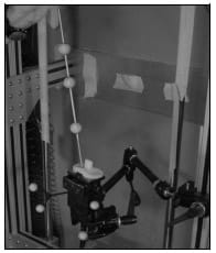
Figure A-1: Picture depicting wanding technique of tibial component. A Bogen arm rigidly
holds the segment in place during the wanding and 4 reflective markers defining
the local coordinate system are rigidly attached.
For each frame of data a least squares rigid body approach was employed to determine the local fixed CS (Challis 1995). For static trials the mean coordinates of the wand tip was used as the divot’s location in the local CS. As a safeguard the distance from wand marker #2 to the vector containing wand marker #1 and #3 was computed and static trials were only kept if the maximum distance was below 0.5 mm. Dynamic wanding trials were visualized within a simple MATLAB GUI that allowed the user to interactively position the CAD file through three rotations and three translations (Figure A-2). Since the dynamically wanded points cover a majority of the implant surface, it was possible to visually “fit” the implant to these points. This allowed an appropriate starting guess to be generated for an iterative closest point algorithm.
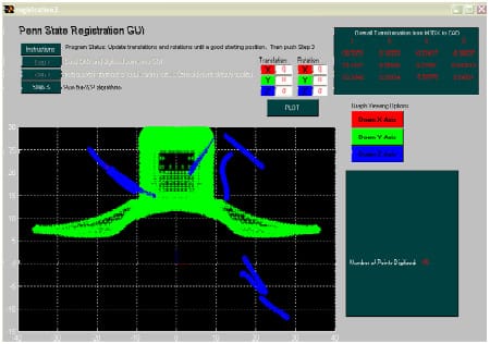
Figure A-2: Screenshot of custom MATLAB Graphical User Interface allowing the user
to visually “fit” the wanded points (blue) to the CAD component (green). Three graph viewing
buttons improve visual feedback and 3 rotations and 3 translations are entered to improve fit.
The user can continue fitting until they are satisfied. The complete 4×4 transformation
matrix is displayed in the upper right corner.
The registration algorithm was developed based upon the work of Besl and MacKay (1992), and it determined the 4×4 transformation matrix from the CAD CS to the local CS. The closed form algorithm minimized the distance from the digitized points to the implant surface. Implant surfaces were defined by importing CAD files (.IGS format) into Rhinoceros 3D solid modeling software (Seattle, WA) and exporting as triangulated meshes (.RAW format) of varying fineness. These .RAW files could be interpreted by MATLAB and used within the registration algorithm.
For each digitized point the closest point on the implant surface, located on either a point, line segment or face, was determined. From this set of closest
points a new transformation matrix (T4x4) was computed within MATLAB based upon the following set of equations:

D = set of digitized points (3xn)
P = set of closest points on implant surface (3xn)
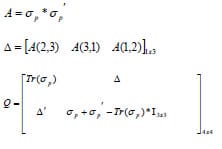
V = eigenvectors of square matrix Q
Quaternion ( qR ) = eigenvector associated with greatest eigenvalue
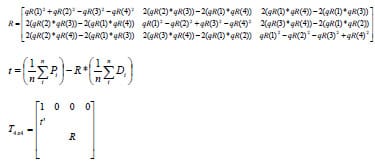
The digitized points could then be transformed into the CAD CS and the corresponding mean distance to the implant surface computed and displayed within the GUI. Subsequently a new set of closest points would then be determined and the next iterative T4×4 determined. This procedure would contain until the change in mean distance values between subsequent iterations was within the user-defined tolerance or a predetermined number of iterations had been met. The algorithm would output the final T4x4 that met the above criteria and the GUI would display the final plot of the implant surface and “fitted” digitized points, mean distance error and maximum distance error (Figure A-3).
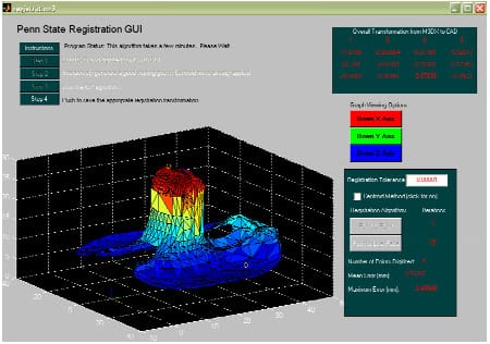
Figure A-3: Screenshot of custom MATLAB GUI showing the final fit of the wanded points
to the CAD component. Mean error and maximum error, which indicates the distance from a wanded point
to the component surface, is iteratively updated as the algorithm progresses. The final 4×4
transformation matrix is displayed before the user pushed the “Step 4” button
that saves the matrix to file.
Although this registration was accurate, it was not repeatable to the necessary magnitude. The final solution was used as a starting guess for an optimization problem. With the 3 rotations and 3 translations describing the spatial relationship between the CAD CS and the local CS serving as design variables, the distance from the divot’s fitted coordinates to their actual coordinates was minimized. A non-linear least squares approach (MATLAB function: lsqnonlin) was utilized to minimize this distance within a few iterations. The complete registration process required approximately five minutes of CPU time.
Repeatability Study
An experimental study was performed to assess the repeatability of registering each individual component. The 4-camera Motion Analysis system was calibrated to a mean error residual of 0.12 ± 0.04 mm. Three separate sets of wanding trials of divots were collected for each component. The component remained rigidly in place between trial sets as it was held by the Bogen magic arm. A registration transformation matrix was calculated for each set of wanding trials. Repeatability was assessed by comparing the origin location and axis rotations of the final registration transformation matrices. The origin offset for all three components was less than 0.64 mm with axis rotation deviations less than 0.5º (Table A-1). The Bogen arm was then repositioned and the component was moved to a new position within the calibrated volume. For a position to be acceptable at least 3 of the 4 cameras must have had a clear vision of each marker. Three separate wanding trials of divot points were repeated and new registration matrices again computed. The mean of this set of registration matrices was compared against the previously computed mean transformation matrix. All repeatability values increased as compared to transformation matrices computed from the same position (Table A-2). These values are more indicative of the true repeatability of the methodology. Although all registrations were able to fit the divot points to a mean error less than 1 mm, the computed transformation matrices had origin offsets greater than 1 mm and potential substantial angular deviations.

Table A-1: Repeatability values of the registration methodology are reported for three wanding
trial sets Each set of trials produced a 4×4 transformation matrix between the CAD CS and the
local CS. Differences between origins and angular differences were computed
and averaged for every combination.

Table A-2: Comparison between registration matrices computed from 2 different locations of each
component. The same divot points were wanded in both positions and a minimum of 3 cameras could
view markers at all times. Values were higher than repeatability trials investigating
the magnitude of wanding error alone (Table A-1).
To assess the meaning of these repeatability values contact between the tibial and femoral component and between the patellar and femoral components was computationally determined using both sets of registration transformations. Following the wanding trials the mechanical knee was assembled and held in a flexed position by the appropriate quadriceps tension. A three-second trial was collected via the Motion Analysis system and the components were computationally reconstructed in the global CS using both registrations. Contact was then determined for both reconstructions and the final contact areas compared (Appendix D). Although the registration values varied slightly, the computed contact areas matched remarkably well with an average overlap of greater than 75% (Figure A-4). The centroid of each contact area was computed and found to vary slightly between registration sets.
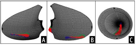
Figure A-4: Computed contact areas on the lateral (A) and medial (B) tibial condyle and the
patellar component (C). Blue areas signify contact area from set of registration matrices, green areas
signify contact area from the other set of registration matrices, while red area represent overlapping
contact area. On average
the overlapping area represented more than 75% of the total contact area
indicating good agreement between sets of registration transformations.
This study indicated that registration of total knee replacement components using a digital motion analysis camera system was possible. Although the repeatability of registration values was fairly considerable, computationally detection of contact area was found to be highly repeatable. Since the detection threshold does vary considerably between registration trials and this value can only be “guessed”, this method on its own does not appear to be a repeatable tool for determining contact area. Despite the difficulty associated with the determination of an appropriate detection threshold, the proposed method was found to be a repeatable protocol for registering TKR components.
APPENDIX B – Dynamic Knee Simulator Modifications
The initial knee rig used within this study has been previously described (Cain 2002). Although no fundamental changes were required of the overall frame design, significant changes were implemented to either create (a) more physiological knee movement or (b) accommodate more sophisticated testing procedures. The following sections highlight and describe in further detail these changes.
- Quadriceps Muscle Actuation: A brush-drive DC motor on a linear cylinder (PL Series; Runyes Corp. via Transnational Source; North Bellmore, NY) with a 9” stroke provided quadriceps muscle actuation. A 12V DC regulated power supply (Extech Instruments Corp.; Waltham, MA) allowed control of displacement rate via input voltage and current. Maximum displacement rate under full load was 5 mm/sec and was regulated via input voltage. A custom built on/off switch including voltage polarity control allowed easy manipulation of the motor in both directions. The motor specifications indicated a 674 lb pull capacity. The motor was rigidly mounted to the side of the rig frame and a custom interface was designed and constructed between the linear shaft of the motor and 5/64” diameter Type 302 stainless steel wire rope 1×19 strand (Figure B-1). The wire rope had greater yield strength, 800 lbs, than the pull capacity of the motor. The custom interface also provided a means of preventing rotation of the linear shaft of motor as it translated. This rotation would ultimately twist the wire rope and lead to its failure.
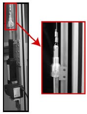
Figure B-1: LEFT – A brush-drive DC motor was rigidly mounted to the rig frame. RIGHT – A custom
designed coupler interfaced the linear actuator and 5/64” diameter stainless steel wire rope. A tracking
device constructed from 80/20-10 series (80/20 Inc.; Columbia City, IN) prevented rotation
of linear shaft during translation. - Quadriceps Tendon Routing: To avoid a complicated system of pulleys to redirect the motor’s actuation, Long Lay conduit (Model C804; Cable Manufacturing & Assembly Co., Inc.; Bolivar, OH) was used to route the wire rope to the femoral segment. The pelvic block was redesigned to allow the conduit to pass, unimpeded, across the hip joint and eliminate any unnatural forces applied to the femoral segment. A custom mount was rigidly attached on the femoral segment to hold the conduit and replicate the line of action of the rectus femoris and vastus intermedius muscles. The mount was designed to allow the conduit to pass over the drill chuck holding the femoral rod.
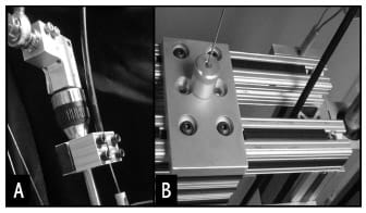
Figure B-2: (A) The Long Lay conduit was rigidly mounted to the femoral rod and allowed to pass
freely above the drill chuck holding the segment in place. (B) A redesigned pelvic block allowed
Long Lay conduit to pass unimpeded through the segment. - Quadriceps Tendon Excursion: In order to measure the amount of tendon excursion a linear position transducer with analog output (Model LX-PA; UniMeasure; Corvallis, OR) was rigidly mounted proximal to the linear actuator (Figure B-3). The transducer had a range of 10”, greater than the expected cable excursion during a knee extension task.
Figure B-3: A linear position transducer was mounted on the tracking 80/20 to measure cable excursion. - Quadriceps Tendon Force: A miniature Omega LCFA-10K uniaxial load cell (Laval, Canda) with 1000 lb load capacity was placed in series with the wire rope. Nylon webbing attached to either the quadriceps tendon (cadaver experimentation) or the patellar component (mechanical knee) was routed around a quick release pin that enabled easy assembly and disassembly of the experimental apparatus (Figure B-4).
Figure B-4: An Omega LCFA-10K load cell was placed in series within the quadriceps tendon. A custom designed and built coupler interfaced the load cell with nylon webbing. The nylon webbing was wrapped around a quick release bolt allowing easy assembly and disassembly. - Hip Joint Load: A custom-built interface was designed to mount a 3-component Kistler quartz force sensor (Model 9251A; Kistler Instrument Corp.; Amherst, NY) proximal to the simulated hip joint center (Figure B-5). This sensor measured forces in three orthogonal axes with minimal cross talk, less than 3%, and an acceptable force range, ±2500 N. The force sensor was mounted under a 25 kN preload to insure that shear forces would be transmitted through static friction across the facing plates. A Kistler 5010 amplifier was used to charge, zero and amplify signals received from the sensor.
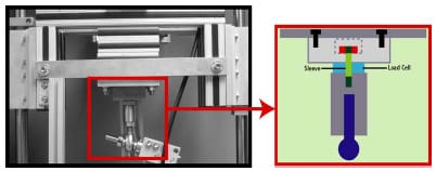
Figure B-5: A 3-component Kistler load cell was inserted to monitor hip joint reaction loads.
Custom mounting blocks were designed and used to preload the load cell prior to its addition. - Counterweight System: A counterweight pulley system was designed to reduce the weight of the pelvic segment and friction experienced within the linear bearings (Figure B-6). An extension was added to the height of the previous rig frame to prevent interference of the hanging weight with a hanging weight simulating hamstring loads (Modification #7). At greater degrees of flexion the requirement of the quadriceps muscle group to extend the knee exceeded the specifications of the linear actuator. As a result of this discrepancy a counterweight system was employed
that enabled extension from flexion angles greater than 60º.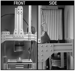
Figure B-6: A counterweight pulley system was added to reduce the load that the quadriceps was
expected to overcome. This was necessary due to limitations of the DC motor specifications and
the need to achieve a greater magnitude of flexion. - Static Hamstring Load: The addition of hamstring load improved the representation of the true physiological knee. The hamstring muscle group had a proximal bony attachment at the ischial tuberoisity. Since the relationship between the hip joint center (HJC) and the ischial tuberoisity was a fixed translation, a pulley was added to the pelvic block in relation to the HJC that approximated the proximal attachment of the hamstring muscles (Figure B-7). Within the mechanical knee 5/64” diameter steel cables attached to the tibial segment were routed around the pulley and a static load was hung.
Figure B-7: A pulley housed within a section of 80-20 15 series was rigidly attached to the
pelvic block. The pulley represented the ischial tuberoisity and the proximal attachment point of the
hamstring muscle group. A static load was hung from the wire rope to simulate muscle force.
This arrangement was utilized for the mechanical knee assembly.
APPENDIX C – Mechanical Knee Specifications
The overall mechanical total knee replacement (TKR) knee design attempted to match physiological measurements whenever possible. Although the mechanical knee represented a simplistic research model, it allowed control of certain experimental variables that would be difficult or impossible within a cadaver specimen. The mechanical knee design was intended to simulate surgical variations, anatomic alignment, and two TKR designs.
Posterior Substituting TKR Design
The femoral shaft was constructed from a 1.27 cm diameter aluminum rod and a greater trochanter to joint line length of ~43 cm. This length was approximated from an average-sized male. An aluminum mounting block interfaced the femoral rod and the femoral component. This block was designed to allow the articulating surface of the component to remain parallel with the ground and for the vector of the femoral rod to pass through the medial-lateral midline of the component. As a result of the aforementioned constraints the mechanical knee featured a 7° quadriceps angle. Since the femoral component mounting block was screwed onto the femoral rod and held rigid with a locking bolt the internal/external rotation of the femoral component could be systematically altered depending on the experimental conditions warranted.
The design of the patella was critical to establishing a valid mechanical TKR model. The overall design attempted to satisfy the following criteria: (1) match residual bone width reported in literature, (2) allow the easy interchange between patellar component designs (either symmetric or asymmetric), (3) allow the ability to alter its position in the sagittal plane (simulates patellar tendon length change), (4) and approximate the typical shape as reported in anatomical textbooks. The patella was designed to have a 24 mm width that matched a study of 337 knees reporting a mean width of 23.6 mm following total knee replacement (Hill et al., 2003). To accomplish these design criteria a three block system was designed (Figure C-1).
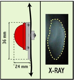
Figure C-1: LEFT – Schematic demonstrating the dimensions of patellar component. Patella was
designed with a 24 mm width and 36 mm length. These values match literature values.
RIGHT – Sagittal x-ray of a typical patella.
The quadriceps tendon (QT) and patellar tendon (PT) were replicated within the mechanical knee with nylon webbing. Selection of the proper nylon webbing was predicated by matching the actual tissue properties and the anatomical dimensions. Harris et al. (1997) reported in a study with cadaver knees that the PT averaged a 3.0 cm width and 0.4 cm thickness. Thambyah et al. (2000) tested the central 1/3 of the PT in 22 cadaver specimens and found that is exhibited a stiffness of 36.5 ± 16.6 kg/mm. A force versus displacement test was performed in a servohydraulic materials testing machine (MTS Systems Corp.; Eden Prairie, MN) on a variety of nylon webbings to best match the actual properties of the QT and PT. The test was conducted at a rate of 1mm/sec with a maximum load set at 1500 N. A linear fit of the elastic region was computed to determine stiffness. Nylon webbing with a width of 2.54 cm and thickness of 0.02 cm (Jontay Distributor; Waycross, GA) displayed a stiffness of 17.8 kg/mm. Since both the stiffness and thickness of this material were approximately ½ of the true PT properties the webbing was doubled-over within the model. This arrangement would better approximate the natural PT and it allowed a quick release of the patellar component from the femoral segment (Figure C-2).
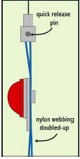
Figure C-2: Nylon webbing was “doubled-up” to better match physiological characteristics of the
quadriceps tendon and the patellar tendon. This arrangement allowed a quick release pin to facilitate
the changing of patellar design.
The tibial segment was designed to meet the following requirements: (1) anatomically matched dimension from ankle joint center to joint line (~43 cm), (2) ability to easily change tibial insert design, (3) ability to set the anterior-posterior position of the tibial insert (4) ability to systematically alter the sagittal height of the tibial tubercle, and (5) ability to systematically alter the anterior-posterior position of the tibial tubercle. Similar to the femoral segment the tibial rod was constructed from 1.27 cm diameter aluminum rod.
Posterior Cruciate Retaining TKR Design
The major difference between the posterior cruciate ligament (PCL) retaining TKR design and a PS knee design featured the retention of the PCL. A 0.58 cm diameter climbing rope (Sterling Rope Company; Scarborough, ME) was mechanically tested within a servohydraulic materials testing machine (MTS Systems Corp.; Eden Prairie, MN) to ensure that the rope had similar stiffness values to those reported in literature (Mommersteeg et al., 1996). In order to compare stiffness values to Mommersteeg et al. (1996) the displacement was converted to strain value. The climbing rope displayed a stiffness of 996N/(mm/mm), approximately half of the value reported by Mommersteeg et al.
(1996). Although this rope was only half as stiff as the natural PCL, it was selected because it best matched both the stiffness and diameter constraints.
The precise location of an oblique hole within the femoral bone substitute (foam) was determined from values reported from literature (Racanelli and Drez, 1994; Morgan et al., 1997; Harner et al., 1999). These hole locations represented the physiological PCL line of action and were designated on a computer-assisted design (CAD) drawing of the foam block (Figure C-3). The Duracon CR (Stryker Orthopaedics; Mahwah, NJ) tibial insert holding piece was designed with a 3º posterior tibial slope and a thru-hole for the PCL (Figure C-4). The Triathlon CR knee design featured a similar design but without the 3º posterior tibial slope. Two slotted holes allowed the anterior-posterior placement of the tibial insert to be adjusted. This feature allowed simulations of surgical variations. A ball bearing cleat (Part # 07481 HAR#150; Harken; Pewaukee, WI), rigidly attached to the tibial segment ~ 3.4 cm below the joint line, allowed active engaging and loosening of the PCL to the tibial segment (Figure C-5). Although the tibial PCL attachment is typically reported as being 1 cm distal to the joint line, the dimensions of the cleat mechanism prevented replication of this parameter. The PCL rope was fixed the femoral segment by passing the rope through the oblique hole in the foam and tying a knot after it exited the hole (Figure 6-3).
A holding piece was machined at Stryker Orthopaedics (Mahwah, NJ) that rigidly held the foam block using four set screws and interfaced with the 1.27 cm diameter femoral rod. The holding piece + foam block screwed onto the femoral rod and was held in place with a locking nut. Since the protocol of Chapter 6 involved the testing of two different implant designs using identical mechanical knee alignments, it was necessary to develop a method at repeatable fixing the internal-external rotation angle of this holding piece + foam block unit. This was accomplished by using two laser pointers rigidly attached to the quadriceps tendon router (Figure C-6). The laser pointers were directed at the superior surface of the holding piece + foam block unit. A piece of laser transparency centered off the screw hole and lateral border was taped to the holding piece + foam block unit. After fixing the holding piece + foam block unit to the femoral rod, two marks were made where the laser pointers hit the top of the holding piece. Before switching to the other TKR implant design, the transparency was centered and taped on the other holding piece. In order to match alignment between knee designs, the holding piece was adjusted until the two marks matched where the laser pointers shone.
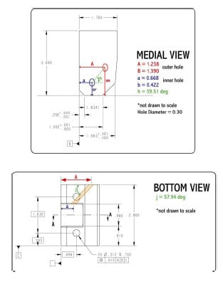
Figure C-3: Schematic illustrating posterior cruciate hole location within foam bone substitute
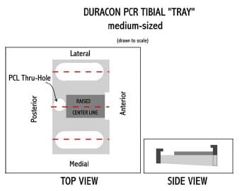
Figure C-4: : Schematic illustrating the design of tibial “tray” for a Duracon CR insert.
A 3º posterior slope was designed into the tray. A PCL thru-hole allowed the climbing rope
to be passed thru the tibial tray. Two slotted holes allowed the anterior-posterior placement
of the tibial insert to be adjusted.
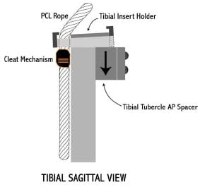
Figure C-5: Sagittal view of tibial PCR segment. A cleat mechanism was used to fix the PCL rope
to the tibial egment. Attachment occurred ~3cm below the joint lie. A tibial tubercle spacer allowed
specifications of the anterior-posterior location of the attachment point and the superior-inferior
degree of freedom allowed simulation of joint line elevations.
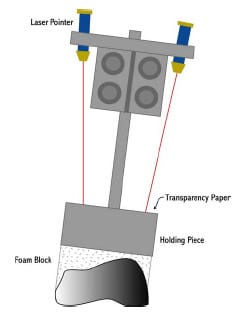
Figure C-6: Laser pointers, rigidly attached to the quadriceps tendon router, were used to
reproduce the internalexternal rotation of femora component between TKR design
APPENDIX D – Computational Determination of Implant Contact from Kinematic Data
The objective of this project was to validate a method for the computational determination of total knee replacement (TKR) implant contact from measured threedimensional kinematics. Since the digital motion analysis (Motion Analysis System; Santa Rosa, CA) used within this dissertation was able to track the centroid of a reflective marker within 0.1 ± 0.05 mm, it was speculated that implant contact could potentially be determined from tracking markers rigidly attached to the tibial, femoral, and patellar segments. Presently the only experimental technique of determining contact areas within TKR involves the insertion of some type of pressure-sensitive film within the joint space. Although this method has been used to measure implant contact, questions have been raised regarding the disruption of true contact with the insertion of a film within the joint space (Wu et al., 1998; Liau et al., 2002). This section outlines the numerous steps taken to validate this method.
The protocol required for validating a method for computational contact detection was extensive (Figure D-1). The protocol was based upon five main steps:
- Implant Registration (Appendix A)
- Computational determination of the signed distance from points located on the tibial insert to the femoral component for a static pose
- Low scale Fuji Prescale film (Sensor Products Inc.; East Hanover, NJ) used to determine real tibiofemoral contact
- Optimization routine to determine an optimal contact detection threshold for which to consider distances computed in step 2 as real contact
- Validation of contact detection threshold was accomplished by using it to compute contact for a new static pose
In order to compute the distance between tibial insert points from the femoral component, implant surfaces required mathematical representations in MATLAB. These steps have been described in Appendix A. Tibial and femoral surfaces were described by a triangulated mesh. For every triangular element, the point, line, and surface normals were computed such that normals for tibial and femoral implants pointed towards one another. Following an implant registration protocol (Appendix A) and the collection of cluster marker coordinates from a static flexed pose of the mechanical knee (Appendix C), a MATLAB program was written to compute the signed distance of tibial insert points (n) to the femoral component could be computed. An nx1 vector of distances was outputted.
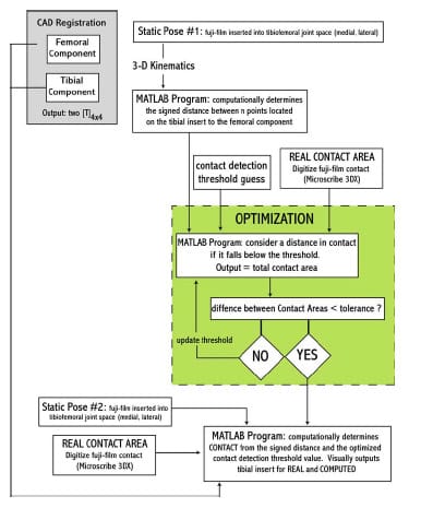
F
igure D-1: Flowchart outlining the steps necessary for validating a computational contact method.
Real contact was determined by inserting Fuji film into the medial and lateral tibiofemoral joint spaces. Films were glued to the tibial insert articulating surface using a commercially available spray adhesive. For a given flexion angle, the mechanical knee was loaded with 18.1 kg compressive axial load applied atop the hip joint center and a 400 N quadriceps force for five seconds. Loads were removed and the joint was disarticulated to prevent artifacts from appearing on the fuji film. A Microscribe 3DX digitizer (Immersion Corp.; Urbana, IL) was used to locate contact areas on both condyles. Fiduciary points within the insert (Appendix A) were used to conduct a separate registration of digitized points to the tibial insert coordinate system CS. A separate MATLAB program was written to determine the vertices of elements within the tibial triangulate mesh that were contacted during the static pose. From the set of “real” contacted vertices the true medial and lateral contact area was computed.
A least squares approach (Levenberg-Marquardt algorithm) was used to minimize the difference between computed contact area and real contact area. The only design variable was contact detection threshold. Since it was expected that a certain amount of error would potentially undermine contact detection, a threshold was essential a “fudge factor” that tuned the method to the real contact. Although this approach ensured matching contact area magnitudes between computed and real, it did not guarantee that contact area location would be the same. Essentially this method would be equivalent to moving the tibial insert in the superior-inferior direction. If too much penetration occurred, then the insert would be moved up (decrease contact detection threshold) and vice-versa. With an optimized threshold the method was found to be accurate both in the magnitude and location of contact areas with contact detection thresholds less than 1 mm (Figure D-2).
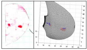
Figure D-2: LEFT – Scanned image of contact area location on fuji film. RIGHT – Triangulated
mesh with real contact (RED) and computationally determined contact (BLUE) with a contact detection
threshold of 0.8562 mm.
Following this optimization set, the protocol was repeated with a new static pose. Contact was computed based upon the optimized contact detection threshold. Unfortunately poor agreement was found when computing real contact area and computed contact area. Either no contact are gross amounts of contact were computed for these poses. Despite repeating the experiment on a number of days with numerous camera calculations, consistently poor results were found for this second static pose.
Before abandoning this approach the following changes were implemented to the protocol to improve the accuracy of this method:
-
- Added a 5th reflective marker to all clusters
- Increased diameter of all three wand markers
- Originally this method was performed with three cameras, but the addition of a fourth camera was attempted
- Implemented a Procrustian technique in the calculation of rigid body kinematics
- Added fiduciary points to TKR implants (Appendix A)
All of these changes were ineffective at improving the accuracy of contact detection. One final attempt at this project was made through the use of a more robust “fudge” factor. It was speculated that the registration of implants may be erroneous in a systematic manner. If this was correct, then a “fudge” transformation could be computed that would compensate for the erroneous registration. Tibial, femoral and patellar CAD files were registered within their respective local CS as defined by a four marker cluster. A static flexed pose of the mechanical TKR model was collected in which it was evident that contact was occurring on the medial condyle, lateral condyle and between the patellar and femoral components. For this static pose the minimum distance at each of these contact locations was computed using the previously explained MATLAB programs. A six design variable optimization approach (simulated annealing) optimized the three Euler angles and three origin displacements describing the femoral registration matrix. Numerous objective functions were attempted, but they were similar in that the algorithm was attempting to minimize the summed distance between the femoral component and the tibial insert and the femoral component and the patellar component. Although this method was able to reduce these three respective minimum contact distances to under 1 mm, no solutions reduced these distances to under 0.75 mm.
APPENDIX E – Micromotion Study Protocol
Data Collection Information
Data Folder: R:Expt324Data41805
A/D Channels: #46: Tendon Excursion #50: Hip Load Fz
#47: Quadriceps Force #51: DVRT 1 (309) [95.7 micron/volt]
#48: Hip Load Fx #52: DVRT 2 (310) [95.8 micron/volt]
#49: Hip Load Fy #53: DVRT 3 (361) [88.056 micron/volt]
Anatomical Control Points: #1: femoral medial epicondyle #5: tibial medial epicondyle
#2: femoral lateral epicondyle #6: tibial lateral epicondyle
#3: femoral rod medial #7: tibial rod medial
#4: femoral rod lateral #8: tibial rod lateral
Test Procedure
——————————————————————————————————————————–
I. RIG & CAMERA SETUP
1.) Calibrate Motion Analysis System
2.) Zero 3-component Hip Load Cell with the femoral head removed
——————————————————————————————————————————–
II. MOUNTING OF FEMORAL COMPONENT
1.) Use a few rubber mallet blows to the tibial component to seat femoral component on foam block
2.) Assess mounting with feeler gauges
——————————————————————————————————————————–
III. MECHANICAL KNEE ASSEMBLY
1.) Screw on foam block, femoral component, and mounting block on femoral rod
2.) Use dry-erase markers to mark wings where DVRTs will contact planks
3.) Attach all 3 DVRT and ZERO
4.) Record time on data sheet to assess how long each block took (may have implications for drift)
5.) Set the AP position of the tibial insert and mark
6.) Set the internal/external rotation of the foam mounting block and mark using laser pointer system
7.) Wand three points from tibial insert (plane1.trc, plane2.trc, plane3.trc)
8.) Wand most inferior point on patellar component (pat1.trc)
9.) Pass PCL through holes and tension using spring scale, record force used
10.) Collect static trial in full extension (TRI_1_static.trc)
11.) run patellaHT.m to calculate patellar height & alter to achieve ~35mm (knee should be in full extension)
12.) Wand Anatomical Control Points in full extension (ACP1-8.trc)
13.) Check knee motion and set side blocks to prevent greater ROM
——————————————————————————————————————————–
IV. COLLECT TRIALS (alternate between foam blocks)
SQUATING TRIALS
1.) Weight of h
amstrings should equal counterweight (10 lbs)
2.) Use clamp on right side rail to set this position throughout the rest of experiment
2.) Monitor Quadriceps force and attempt to match between trials
3.) Collect 10 extension trials (TRI_1_S1.trc – TRI_1_S10.trc)
GAIT TRIALS
1.) Counterweight should be removed and 35 lbs added to pelvic segment
2.) Use clamp on left side rail to set this position throughout the rest of experiment (~20 flexion)
3.) Monitor Quadriceps force and attempt to match between trials
4.) Collect 10 extension trials (TRI_1_G1.trc – TRI_1_G10.trc)
——————————————————————————————————————————–
V. REMOVING FOAM BLOCK
1.) Be sure to write down ending time of foam block on data collection sheet
3.) Be sure to check that contact point between each DVRT and plank has been marked
4.) Remove DVRTs from foam block
5.) Undo quick release on patellar component
6.) Unscrew foam block from mounting block
7.) Remove PCL rope from block
——————————————————————————————————————————–
VI. MICROSCRIBE 3DX
1.) Place foam block & femoral component in Bogen Arm
2.) Establish Microscribe coordinate system using three divot points
3.) Redigitize three divot points (origin, x-axis, y-axis) (cs1.txt)
4.) Digitize 3 DVRT contact points with wings (wing1.txt)
5.) Digitize femoral component border points on foam on anterior cut face (Acuts1.txt)
6.) Digitize femoral component border points on foam on posterior medial cut face (PMcuts1.txt)
7.) Digitize femoral component border points on foam on posterior medial cut face (PLcuts1.txt)
8.) Remove femoral component
9.) Reestablish Microscribe coordinate system using three divot points
10.) Redigitize three divot points (origin, x-axis, y-axis) (cs1a.txt)
11.) Digitize femoral component interior points on foam on anterior cut face (Acuts1a.txt)
12.) Digitize femoral component interior points on foam on posterior medial cut face (PMcuts1a.txt)
13.) Digitize femoral component interior points on foam on posterior medial cut face (PLcuts1a.txt)
14.) Remove planks from wings
——————————————————————————————————————————–
VI. NEXT FOAM BLOCK
1.) Repeat Part II
2.) Repeat Part III 1-4, 9, 10 (in blue text)
3.) Repeat Part IV, V, VI
——————————————————————————————————————————–
VII. SWITCH KNEE DESIGN
1.) Swap tibial inserts & be sure to match the AP dimension
2.) Swap patellar component & be sure not to disrupt markers
3.) Remove femoral mounting block and be sure the lasers dots have been marked & # of nut revolutions noted
4.) Tape transparency to new femoral mounting block
5.) Screw on new femoral mounting, align with laser dots and tighten with nut (same # of revolutions)
6.) Go to Part VI and test 5 foam blocks
——————————————————————————————————————————–
VIII. DATA PROCESSING OVERVIEW
1.) MATLAB code
a.) ACP.m: creates anatomical CS
b.) process1.m: processes one extension trial & plots micromotion vs knee flexion
c.) processALL.m: processes 10 extension trials & plots micromotion vs knee flexion
d.) wingROTATION.m: computationally determines micromotion on a cut plane
——————————————————————————————————————————–
About the Author
Matthew Moran graduated magna cum laude from the College of William & Mary (Williamsburg, VA) with his B.S. in Kinesiology (’98). During his undergraduate career Matthew investigated ground reaction force and center of pressure patterns of mild Parkinson Disease patients. Before beginning his graduate studies Matthew taught secondary mathematics at his high school alma mater, Saint Anthony’s High School (South Huntington, NY) from 1998-2000.
Following this brief teaching stint, Matthew attended The Pennsylvania State University (University Park, PA) in the Department of Kinesiology at the Center for Locomotion Studies under the mentorship of Dr. Stephen J. Piazza. His master’s thesis (’00), Biomechanical Investigation of Split Tendon Transfers for the Treatment of Hindfoot Varus, utilized both cadaver and musculoskeletal modeling software to test the effectiveness of a number of common surgical variations used in cerebral palsy and stroke patients. This research project was supported through a Whitaker Foundation Grant. This work was presented at several academic conferences, was published in the Journal of Bone & Joint Surgery (85-A(5):858-65) and the Journal of Pediatric Orthopedics (24(3):298-303), earned Matthew the department’s 2003 Graduate Student of the Year award, and placed 2nd in the Health Sciences portion of the 18th annual Penn State Graduate Exhibition. Matthew earned an Academic Computing Fellowship, one of the most prestigious scholarship awards offered through The Pennsylvania State University Graduate School, to support his doctoral work. He completed his doctoral course work with 4.0 GPA.
During his time at University Park, Matthew also served as Penn State’s volunteer assistant cross country/track & field coach, taught select lessons of an undergraduate course (Mechanics of Locomotion), and led a group of select undergraduate students through an intensive human cadaver dissection. After completing his dissertation Matthew plans on remaining in academia and continuing with research in the field of computational biomechanics through both teaching and research initiatives. In his spare time Matthew is an avid runner and was the top American finisher in the 2002 Athens (Greece) Marathon.


