K. Ogawa and T. Yokoyama*
Division of Aeronautics and Astronautics, Graduate School of Engineering,
Kyoto University, Yoshida Honmachi Sakyo-Ku, Kyoto 606-8501, Japan
*Department of Mechanical Engineering, Okayama University of Science,
1-1 Ridaicho, Okayama 700-0005, Japan
Abstract
To characterize damage and deformation in an impacted area of structure caused by flying foreign objects, it is fundamentally needed to measure the acting force and its pressure distribution over the area. In the present investigation, we attempt to visually identify the impact force by means of the pressure sensitive paper which is a combination of papers coated by micro-capsules containing coupler and developer, and is currently used for measuring the quasi-statically applied force on the bodies in contact. A split-Hopkinson pressure bar method was used to evaluate the sensitivity of the paper under impact loading. Dynamic impression marked on the paper was digitized by a scanner, and the color density was measured by the FPD901 electronic densitometer system. It was found that the pressure sensitive paper instantaneously responded even for the impact loading of which duration was several hundred microseconds, while the sensitivity was significantly reduced when compared to the quasi-static loading. As for an example, we applied the method to evaluate the impact force in the dynamic response of a golf ball and discussed the results.
1. Introduction
To clarify the damages and deformation in structures subjected to collision of high velocity foreign objects; it is a fundamental requirement to identify the magnitude and the distribution of pressure on the impacted area on the structures. Recently, a measurement of impact force using piezo-electric film is reported[l], while there has not been developed an appropriate method to directly measure two-dimensional pressure distribution over the impacted area. Especially from an engineering view point of damage protection, evaluation of maximum pressure experienced during impact must be greatly concerned.
The pressure sensitive paper coated by micro-capsuled coupler [2,3] is developed under pressure and is well known as a non-carbon type copying paper. The paper is used to mark an impacted point on a bat in baseball and on a head of golf club, but still it is not succeeded to evaluate impact force and its dynamic pressure distributions. The paper in the present investigation is coated by coupler capsuled in various sizes as shown in Fig. 1, and is developed in corresponding depth of color to applied pressure. Microstructure of the paper is shown in Fig.2, and the combination of various sized micro-capsules can be seen, since smaller capsules may fracture at higher pressure.
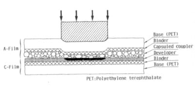
Fig. 1 Structure and mechanism of pressure sensitive paper
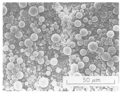
Fig.2 Microstructure of pressure sensitive paper by SEM
The paper is widely used to sense the quasi-static pressure of which loading rate is in the range of a few minutes to several seconds, while there has not been reported any attempt to measure the impact pressure of short duration such as several hundred microseconds. Since fracturing of micro-capsules significantly depends on the temperature and the humidity, it will be relevantly needed for visualization of impact pressure to clarify the effect of loading rate on the relations between the pressure and the depth of developed color as well.
The present paper describes dynamic response of pressure paper and its sensitivity clarified by means of a compressive split Hopkinson pressure bar[4]. As an example, the present new technique using pressure sensitive paper was applied to the dynamic pressure measurement of golf-ball impact, and the results were fully discussed.
2.Specimen and Experiential Procedures
Two kinds of pressure sensitive paper, type-MW and type-MS for intermediate pressure, were tested [5]. In the case of the type-MW, coupler and developer in various sized micro-capsules are separately coated on respective sheets, while the microcapsuled coupler and developer are both coated on the same sheet in the case of the type-MS.
Impact pressure is applied using a split Hopkinson pressure bar apparatus as shown in Fig.3. An input and an output loading bars of 20mm in diameter are smoothly supported by slide bearings as indicated in the figure, and the both ends are sufficiently flattened to obtain homogeneous impact pressure over the test area. To minimize a possible bending moment inevitably encountered in this kind of experiment, the bars are carefully aligned, and an end of the striker bar is slightly rounded to make contact with the input bar at the center of the impacted surface. The pressure sensitive paper is inserted between the input and the output bars as shown, and several trial impacts are applied before the test to ascertain a good contact over the test area by checking an impression left on the paper.
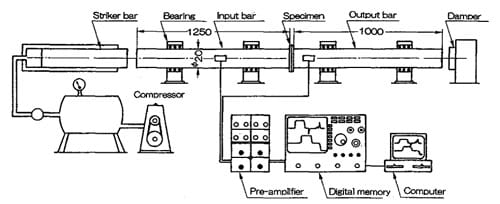
Fig.3 Compressive split Hopkinson bar apparatus and measuring circuit
An incident, a reflected, and a transmitted stress waves, σI, σR, and σT, respectively, are sensed by the strain gauges given in the figure , and are recorded in a multi-channels transient recorder in digital form. The impact pressure, Pa, is evaluated by the following equation as; (1)
Pa = ( σI + σR + σT) / 2
A developed color mark left on a pressure sensitive paper is scanned by a pressure image digital analyser FPD-901 of which spatial resolution is 0.25mm square, and the pressure, Pa, is evaluated using the calibration curve of depth of color to pressure given by the supplier.
3. Results and Considerations
Fig.4 shows an example of the incident, reflected, and transmitted stress waves detected by the strain gauges. The rectangular shaped incident wave of 10 ~ 15μs sharp rise time is applied to the specimen, and the corresponding transmitted stress wave of almost the same magnitude and duration propagates to the output bar. Only at the beginning of the loading, a small amount of reflected wave is detected due to a possible initial clearance between the specimen and the loading bars. Thus, the specimen is compressed fo
r about 200μs under impact.
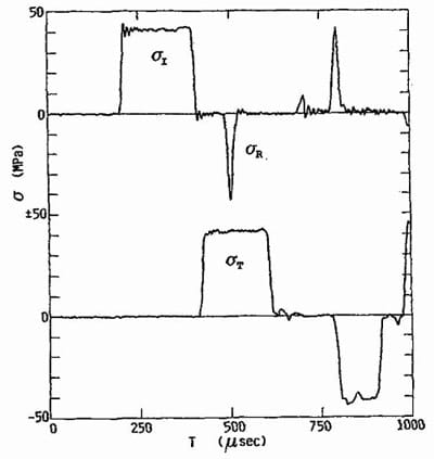
Fig.4 Incident, reflected, and transmitted Stress waves in tests
Fig.5 represents an example of the impressions left on the paper, MW, and the pressure distributions are shown by coloring. The size of impression is slightly larger than that of the loading bar, and this may be reasonably understood by considering additional surrounding excess regions on the edge of the pressured area probably formed due to squeezing out of couplers. The area of this impression is evaluated as 325mm2, while the area is reduced to 303mm2, when the area of pressure less than 1OMPa, the minimum sensitivity of pressure, is excluded. Therefore, about half of the area of pressure less than 1OMPa should be reasonably counted as the contact area, since the area of the loading bar is 314mm2. Thus, it is somewhat difficult to ascertain the true contact area, but it may be verified that the pressure sensitive paper can promptly respond even for the impact pressure.
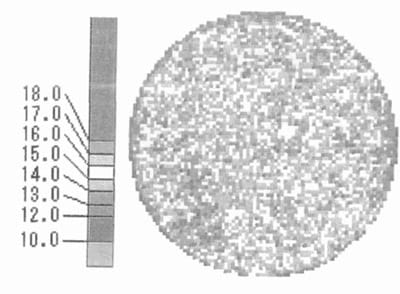
Fig. 5 Colored impression digitized by electronic densitometer
The distribution of the pressure is not perfectly uniform over the impacted area and it is noted the depth of color is slightly lighter in the edge area. Fractions of respective areas at pressure, Pe, evaluated are shown in Fig.6, and half value width at the maximum measures ±2MPa as for the accuracy of the experiment. Therefore, even though the pressure does not distribute perfectly uniform, the averaged value over the area is used for the pressure Pe for the respective applied pressure.
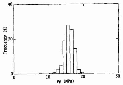
Fig.6 Fraction distribution of pressure over an impression in dynamic test
Fig.7 shows the relations between the applied pressure Pa and the evaluated pressure Pa for the respective specimens. In the case of the MW, measured depth of color is dependent on the time elapsed after the test, and solid circles represent the data measured at 1Omin after loading, while there is not any significant change of depth in the case of MS during measurement. The open circles indicate the values obtained at about 103min after impact both for the MW and MS. A single curve can be drawn for the respective materials, and can be used for visually evaluating impact pressure through measurement of color depth developed on the pressure sensitive papers.
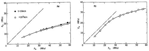
Fig.7 Relations between the applied pressure, Pa, and the evaluated pressure, Pe,
for MW- and MS-type pressure sensitive paper
It should be noted that the depth of the color is significantly reduced in the case of impact pressure comparing to the static loading, and consequently, the evaluated pressure is always lower than the applied pressure. Especially in the high pressure range, depth of the developed color does not increase both for the materials, and sensitivity in this range is much less than the low pressure range. This fact indicates that fracture stress for smaller capsules much more significantly depend on the duration of pressure; shorter the duration, higher the fracture stress. In the case of the MW, sensitivity is less than the MS, and this may be due to insufficient contact time for coupler to be developed in such a short duration as 200μs. Therefore, it is not adequate to evaluate impact pressure using the given calibration curves obtained for static pressure.
4. Application to Golf-Ball Impact
4.1 Experimental procedures
Fig.8 shows the experimental set-up for golf-ball launching device [6]. Three pieced balls of 42.7mm in diameter and of 45.4g in weight were used. The balls were carried by a nylon sabot and were fired by compressed air onto the end of the long target bar. Impact force in the bar was sensed by the strain gages cemented at the position and was memorized in digital form through the pre-amplified electric circuit. Velocities of impact and restitution of a ball were measured by the velocity measuring unit of a pair of photo-diodes as shown in the figure. On the end of the target bar, the pressure sensitive paper of type-MS was placed, and the impression of the ball was recorded.
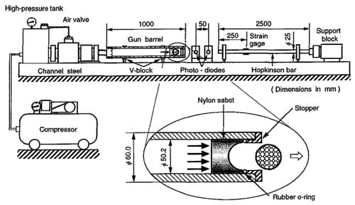
Fig.8 Experimental set-up for golf-ball launching device
4.2 Results
Fig 9 examples the load-time records detected by the strain gauges on the target bar. When the initial velocity of the ball is increased, the maximum load is promptly increased, while the duration of impact is kept almost constant (about 500microseconds) independent of the initial velocity.
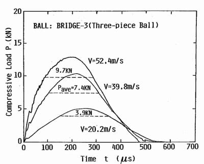
Fig. 9 Load-time records detected by strain gages on the target bar
Figs. 10 (a) (b) represent the impressions analyzed at narrow and wide ranges of sensitivity, respectively in the case of the initial velocity of 39.8mJsec. In Fig.10 (a), two kinds of open circles correspond to the dimples on the ball and high pressure clearly exists in the central region, spreading towards outside gradually decreasing its values. Inside of almost all dimples in Fig 10(b) are represented in blue due to subjecting to pressure This fact suggests that the air trapped in the dimples is compressed during impact, and also sustains the pressure in some extent. It is noticed that a high pressure is attained in the central dimple where a large deformation is expected. Total load evaluated through the present calibration curve as shown in Fig.11 measures about 6.7KN which is lower than the observed peak value of 10.3KN, while the calculated value of 4.4KN using the calibration curve given by the supplier is significantly underestimated. The same kinds of results are also obtained: the loads of 8.7KN and 3.2KN were evaluated by the present calibration curve for the velocities of 52.4m/s and 20.2m/s, while the corresponding peak values of 12.8KN and 5.OKN by the given curves in Fig.9. Thus, the load evaluated by the pressure sensitive paper is still not satisfactory, even though using the present calibration. One of the reasons for this discrepancy may be understood by taking account of impact duration.
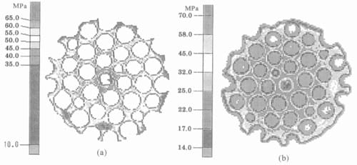
Fig. 10 Colored impressions in a golf-ball impact
Since the result shown in Fig.7 was obtained for the impact duration of 200μsec, it would be necessary to estimate the average load of which duration is as the same. In Fig.9 the horizontal broken lines indicate the average load, Pave, yielding 9.7KN, 7.4KN, and 3.9KN for the impact velocities of 52.4m/s, 39.8m/s, and 20.2m/s, respectively. The evaluated values from the pressure sensitive paper are almost satisfied, even though they are still slightly (about 10%) lower than these average values. It is reasonably
understood that the peak load in the impact is difficult to be detected by the present technique, since the duration of the peak load is much shorter than 200μsec. Further experiments would be needed to confirm the effect of impact duration on the pressure to depth of color relations, together with finding the appropriate method to measure the impact duration. One of the methods is a dual-sheet technique as schematically represented in Fig. 11. In general, duration of impact, such as T1, T2, T3, changes the relation of pressure to depth of color for the respective papers as shown in the figure. Two kinds of pressure sensitive papers of the different pressure-depth of color-relations are layered on the contact surface. When the color densities of a and b are recorded, we can find the point where the pressures (Pa3, and Pb3,) and the duration of impact (T3) are identical both for the papers.
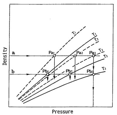
Fig. 11 Schematic presentation of dual-sheet method to
simultaneously evaluate duration and magnitude of impact
5. Conclusions
The impact compression test on the pressure sensitive paper was carried out to clarify the sensitivity and the response for impulsive pressure to realize visualization of impact force. The results obtained are summarized as follows.
- The impact pressure of several hundreds microsecond duration can leave colored impression on the pressure sensitive paper, and can be visually detected.
- Although depth of the color marked under impact pressure is much lighter than the case of quasi-static pressure, the relation between the depth of the color and the pressure can be uniquely determined even for the impact pressure.
- The relation obtained can be applied to identify the pressure distribution in the dynamic contact of flying objects.
References
- Smith A.L. and Mee D. J., J.Strain Anal.Engng.Design,31, (1996)463-483.
- Moriga H., Introduction to chemistry of Special Papers,(Kobunshikankoukai, Japan,1975) pp.24-50.(in Japanese)
- Nakamura K., J. Paper and Technology Jpn., 29,(1975)9- 15,(in Japanese)
- Hauser F.E. et al.., ” Response of Metals to High Velocity Deformation”,(l961), Ed.by P.G.Shewmon and V.F. Zackay Interscience Pub.,N.Y. pp.93-103.
- 0gawa K., J. Soc. Mat. Sci. Jpn., 47,(1998)20-25,(in Japanese)
- Yokoyama T., Proc. 31st Symp. Stress-strain Meas. Strength Eva1.(2000)145-150, Jpn.Soc. Non-Destr. Insp.


