The Lamination Process is an operation where two or more layers of material are permanently joined together. For example, one can perform the process of lamination by placing a flexible material, such as paper, between layers of plastic and gluing the assembly with heat, pressure, or adhesive to form a durable sandwich. Common laminates are drivers’ licenses, plywood, engineered flooring, or kitchen counter tops.
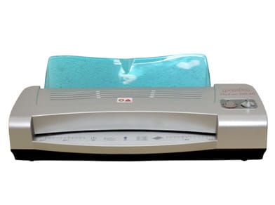
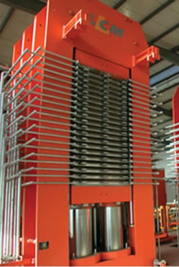
Figures 1 through 3 illustrate examples of lamination processes. Figure 1 is a picture of a desktop laminator. Figure 2 shows a multi-layer laminating press. Laminating presses are manually-operated hydraulic presses with stacked heating and cooling platens. They are used to manufacture lumber, metal, and paper products. They may have multiple openings and feature precise controls for temperature and pressure. The platens may be heated by steam, oil, or electricity.
 |  |
| Fig 1: Desktop Laminator | Fig 2: Multi-layer Lamination Press |
![]()
Fig 3: Calender or Hot-roll Lamination Equipment Schematic
Figure 3 shows a schematic of calender or hot-roll lamination equipment. This type of lamination uses a heated, three-roll stack to activate an adhesive film, which is applied to the substrate. Material selection and pressure control is critical to obtaining a strong, long-lasting bond between the film and the substrate.
Printed circuit boards are produced using this lamination process. However, insufficient or non-uniform pressure can lead to wrinkles or other defects as shown in Figure 4. Such defects can result in costly rejects as well as premature product failure.
Because of these potential problems, it is desirable to have a way of measuring the pressure between the rolls. Prescale, Pressure Indicating Film, measures the actual pressure profile between the rollers. The film is placed between the two rolls before closing the gap between them. (See Figure 5.)
Fig 4: Lamination Wrinkles due to
Uneven Roll Pressure
Fig 5: Prescale Placed between the Top Roll and the Printed Circuit Board
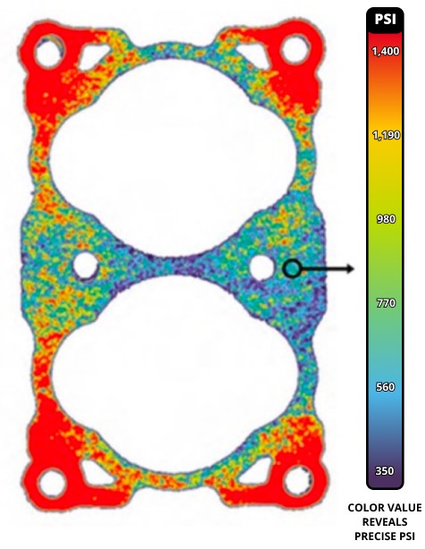
When pressure is applied, one can observe the image captured by the Prescale as shown in Figure 6.

Fig 6: Pressure Profile between Top Roll and Printed Circuit Board.
Obtained Using Prescale and Topaq Analysis.


