Jan Krmela1,*, Libor Beneš2, Vladimíra Krmelová1
Dr. Ir. I. Lopez Arteaga
1 University of Alexander Dubcek in Trencín, Faculty of Industrial Technologies, I. Krasku 1809/34, 020 01 Púchov, Slovak republic.
2 University of Pardubice, Jan Perner Transport Faculty, Studentská 95, 532 10 Pardubice, Czech republic.
*corresponding author: e-mail: [email protected]
Resume
The article deals with the statical experiments of tires for obtaining material parameters and deformation characteristics by tensile testing machine and also special statical testing tire machine. The tires consist of polymer matrix – rubber and long-filament reinforcement – cords, hence the tires are fall within as very complex long-fibre composite with specific deformation characteristics. These tire deformation characteristics have given geometry shape of tire and material parameters of component parts of tire-casing. Nowadays the computational modeling is used for tire solutions and experiments are subsidiary only. But the combination of computational modeling with experimental approach is necessary to use for prediction real states of tires. For computational modeling of tires the material parameters of each component part of tire-casing are necessary as material input data for computational models. These material parameters can be obtained by tensile test by statical testing machine. The geometry parameters of multi-layer test specimens of steel-cord belt with conditions of tensile tests are designed. The data from statical deformation characteristics are necessary for comparison of computational outputs with experimental data. The special testing tire machine called statical adhesor is used to obtain deformation characteristics and information about contact patches with pressure distribution in contact patches. The experimental results of chosen radial tire 245/40 R18 for passenger car are presented in this article. In this paper a new formula for calculating of value of radial stiffness is designed too.
Introduction
Tires for road transport are only one interface areas between car and road. The function of tires is not only to align a car reliably. The main requirements on tires are high wear resistance, optimal deformation characteristics, low rolling resistance, high operational life and safeness, etc. Then requirements on the tires Fig. 1 are very high [1, 2].
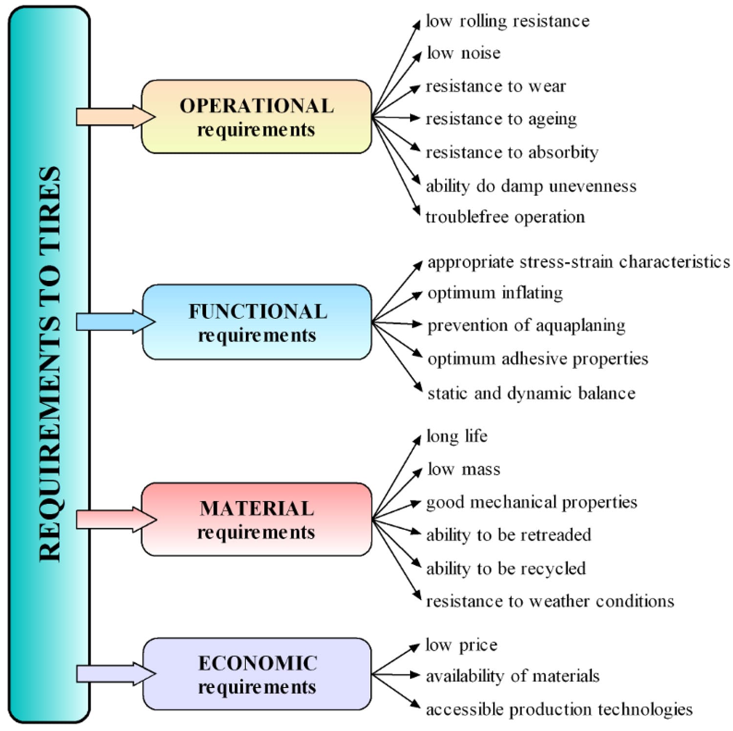
Fig. 1. Requirements on tires
Safety of the road transport depends on the quality of tire production, next quality of materials for tire production and internal construction of tires namely.
Tire is during the operation exposed to combined loading as from a mechanical (statical, dynamic) as a temperature point of view (local heating in subzones, overall heating in the tire-tread area permeating into the tire during breaking) [2]. Also this has to be considered in defining tire safety at high speeds. Generally tires are supposed to be exposed to surroundings effects, we observe their undesirable appearance changes and mainly mechanical quality changes after a certain time, the surroundings range which affect the tire during its lifetime is wide. For long life of tires they must be resistant to surrounding effects.
Tires have different construction depending on the type of road transport. Tires can be classified as complex long-fibre composite consisting of polymer matrix – rubber (elastomer) and long-filament reinforcements – cords.
The basic composite structure parts applied into tires for road transport e.g. for agricultural machinery are [1]:
- Textile-cord carcass,
- Textile-cord overlap belt,
- Steel-cord belt.
These tire structure parts are differentiated by:
- Geometry parameters of tire,
- Numbers of reinforcing plies,
- Construction of belts and cord-angles,
- Width of belts,
- Material and construction of cords etc.
The article is oriented to radial tires for passenger cars. The cross section structure of radial tire 245/40 R18 into tire crown is represented by Fig. 2 as sample.
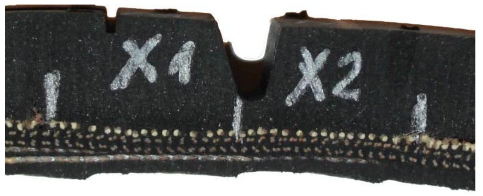
Fig. 2. Structure of cross section of tire-crown of radial tire for passenger car
Necessary statical experiments for computational modeling of tires are:
- Experiments of each component part of tire-casing for obtaining material parameters and their using as input to computational models of tires,
- Experiments of tires on testing machine – statical adhesor for obtaining statical deformation characteristics namely radial deformation characteristic which will be used for verification analysis between computational outputs with experimental data.
Statical experiments of component parts of tire
Knowledge of the behavior of elastomer parts and composites as belts under mechanical load is necessary too. These data are obtained by experimental modeling of composite specimens and composite component parts of tire (matrix and reinforcement) by:
- Static tensile tests,
- Compression tests,
- Shear tests,
- Bending tests,
- Tests under combined loading states (e.g. combinations of tensile with bend) – that are to be approximated tire real states during tire operational loading,
- Tensile tests after previous corrosion tests.
Experiments, namely tensile tests, of specific long-fiber composite materials with hyperelastic matrix (e.g. tire steel-cord belt) are not standardized.
Shapes and dimensions of test specimens are not determined by standard. Only for current laminate composites the standard exists [3]. For determination of material parameters of rubber matrix and cord-reinforcements experiments are necessary to be made in agreement with standard specifications. These parameters should be different in each specimen:
- Material of cord (surface treatment),
- Form of cord (wire, thin wire),
- Angle of cord (with respect of the direction of loading – not only longitudinal and transverse orientated specimens),
- Number of layers (single-layer, two-layer, multi-layer),
- Specimen width, shape etc.
The author Krmela designs to use multi-layer test specimens with different width of 10, 15 and 25 mm and of length of 120 mm and also with different angles and number of layers. The statical testing machine withou
t extensometer was used for experiments.
The conditions of the tensile tests are:
- Starting value of length between clamps of test machine 92 mm,
- Elongation measured on the same length,
- Loading speed 10 and 25 mm/min.
- The conditions of the bend tests are:
- The value of distance between outside points was 50 mm,
- Loading speed 5 mm/min.
The Fig. 3 presents stress-strain dependencies for chosen layers of steel-cord belt as sample outputs from tensile tests after corrosion tests. Photographs of specimens with No. EE3 and FF3 are on the Fig. 4 and detail of crack on specimen No. EE3 on the Fig. 5. The specimens have symmetrically and non-symmetrically cord-angles structures.
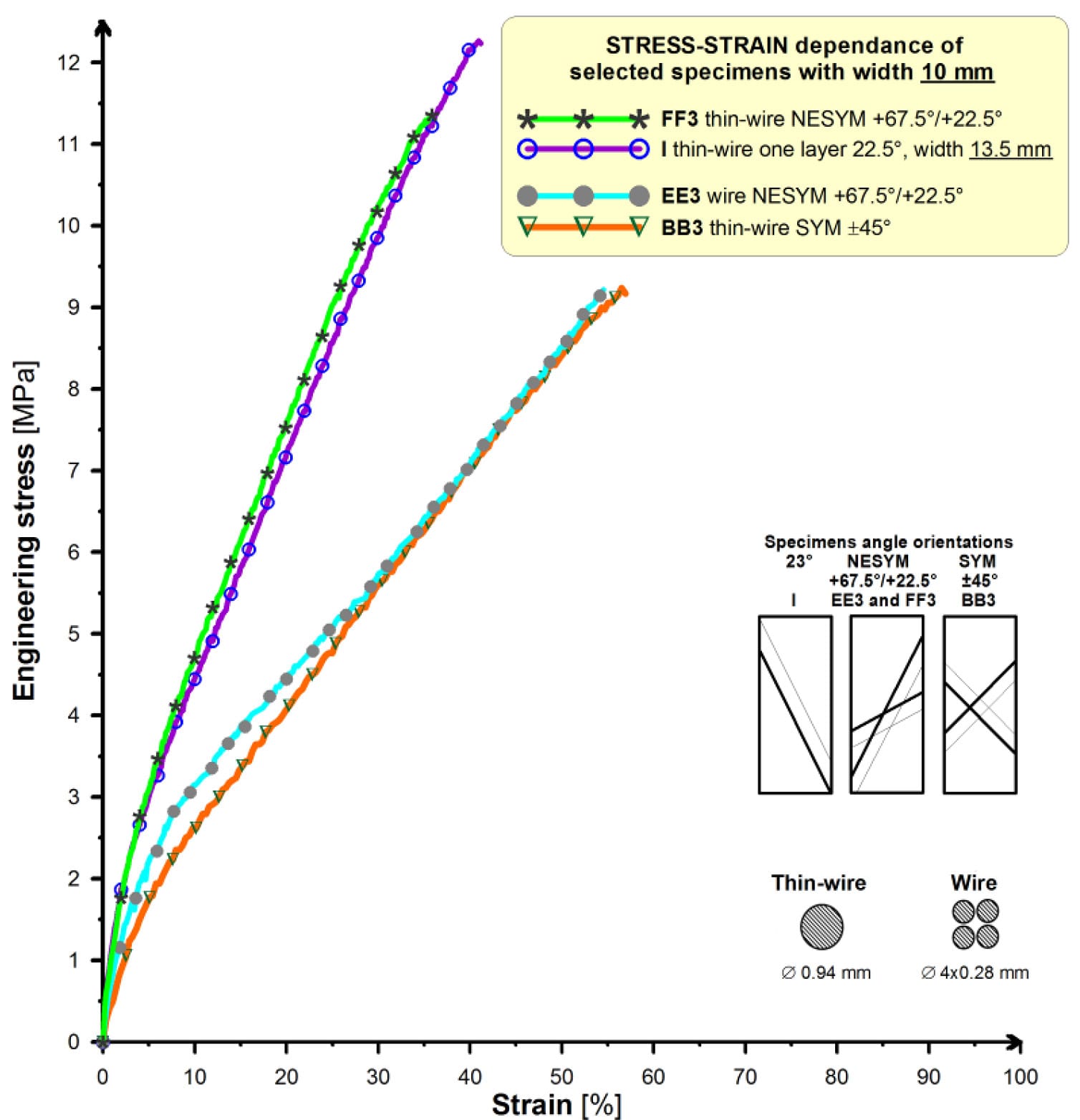
Fig. 3. Stress-strain dependencies as outputs from tensile tests of steel-cord belt specimens with different cord-angles
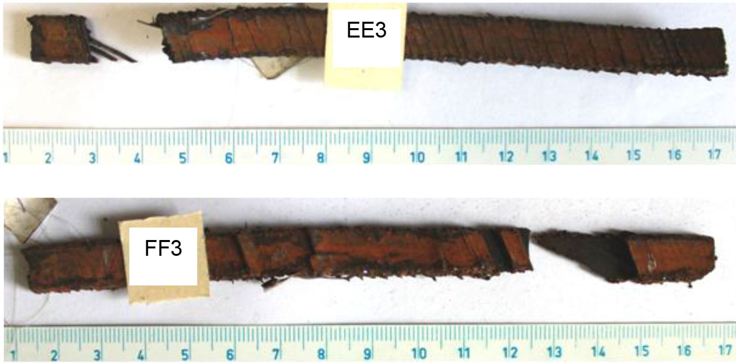
Fig. 4. Specimens No. EE3 and FF3
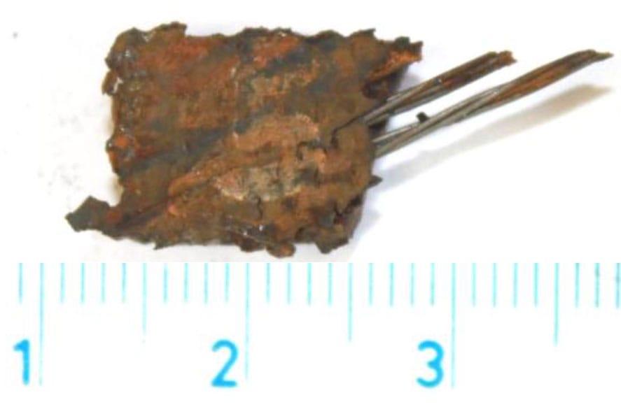
Fig. 5. Detail of crack on specimen No. EE3
Other tests of whole structure parts of tire into crown of tire-casing are necessary for obtaining material parameters of steel-cord belts with textile-cord carcass and tread as one unit. Detail of cord structure in tire crown of real tire on Fig. 2 is presented by Fig. 6.
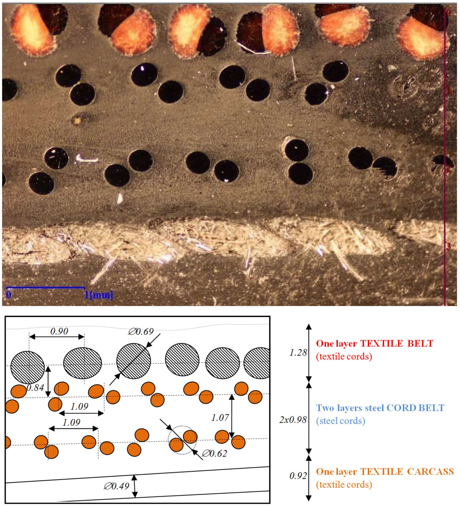
Fig. 6. Detail of cord structure into tire-crown with geometry parameters
The construction of steel-cords is 2×0.30. The specimens were prepared by water jet with:
- Different width – 10, 15 and 20 mm,
- Different directions – longitudinally and transverse,
- With or without tread.
Fig. 7 presents specimens No. C, E and G with longitudinally direction and different width. The specimens No. J, K and I with transverse direction and different width are on the Fig. 8. The tensile and bend tests were performed on the specimens with aim to obtain modules of elasticity in different directions of configuration of specimens.
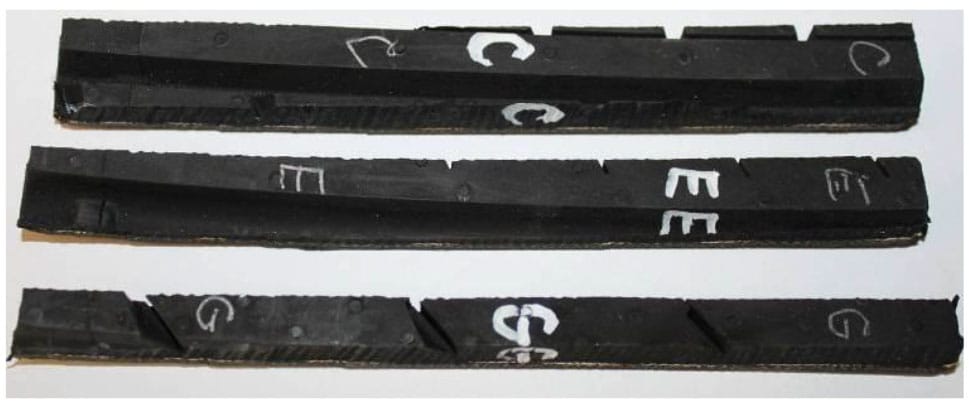
Fig. 7. Specimens of tire 245/40 R18 with longitudinally direction with different width for tensile and bend tests
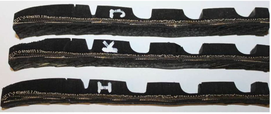
Fig. 8. Specimens of tire 245/40 R18 with transverse direction with different width for tensile and bend tests
The conditions of the tensile tests are:
- Starting value of length between clamps of test machine 100 mm,
- Elongation measured on the same length,
- Loading speed 10 mm/min.
Outputs from experiments of above selected specimens are presented on Fig. 9 by stress-strain dependencies. Modules of elasticity as outputs from experiments for use as input data to computational models are in Table 1.
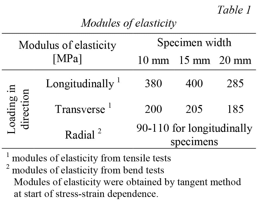
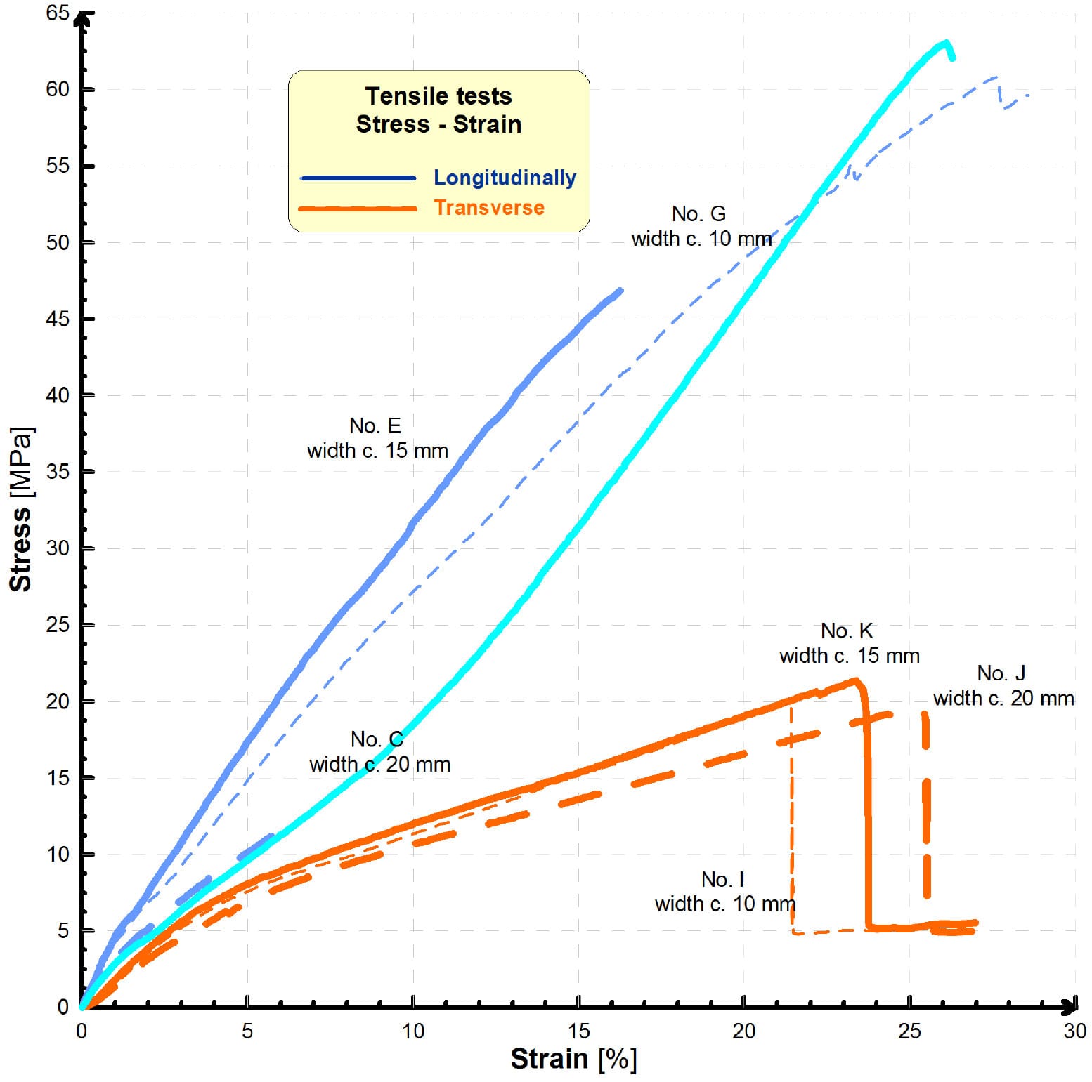
Fig. 9. Stress-strain dependencies from tensile tests of tire-crown specimens with different width
The homogenization of systems cord – elastomer into tire is required. Different descriptions of composite component parts into tire computational models are possible, see Fig. 10. Values of modules as inputs to computational models of concrete tire (if area of tire crown describes as homogenous material with orthotropic material model) are on the Fig. 11.
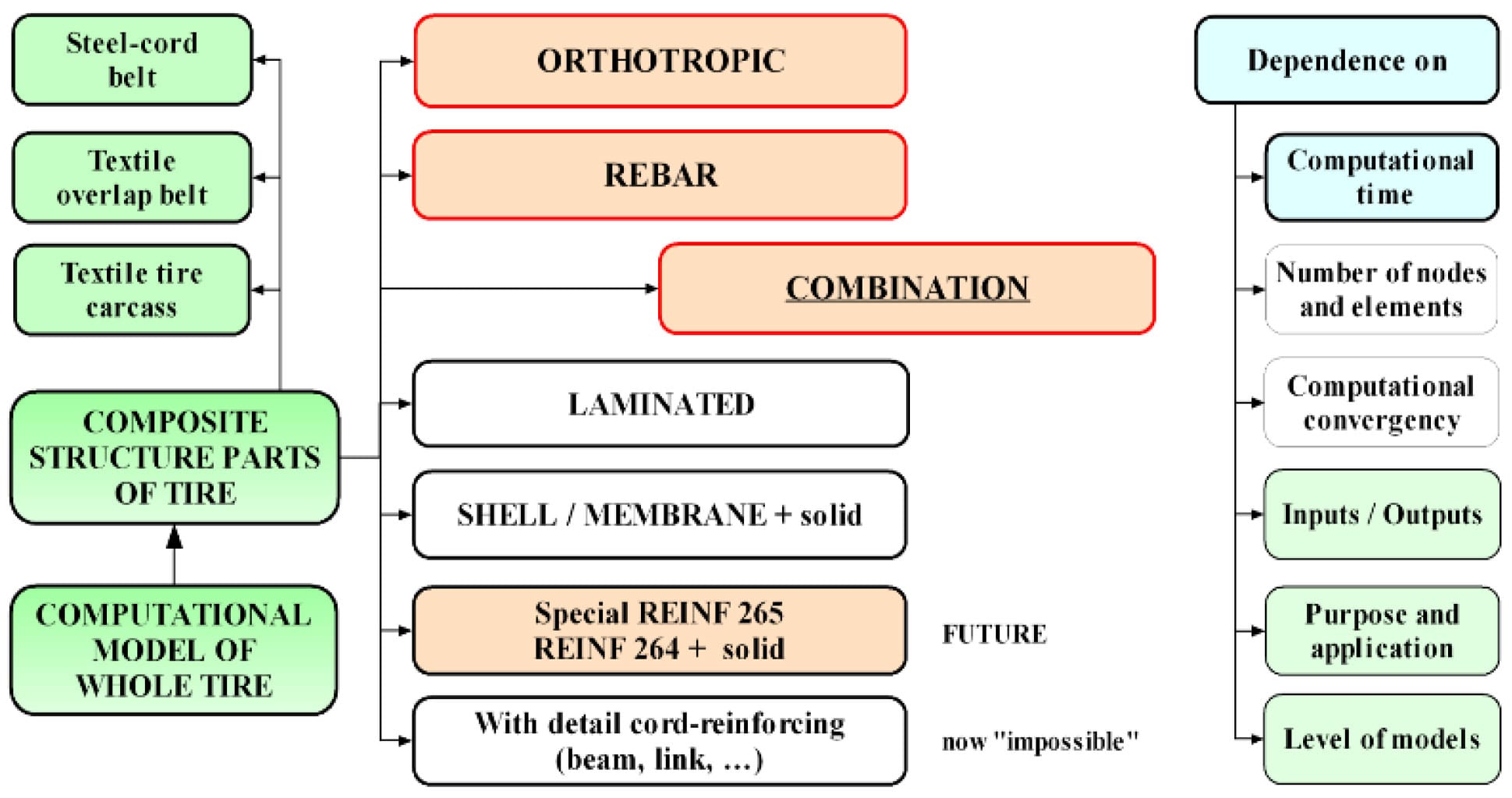
Fig. 10. Methods for descriptions of cord – elastomer structure parts for computational models of tires
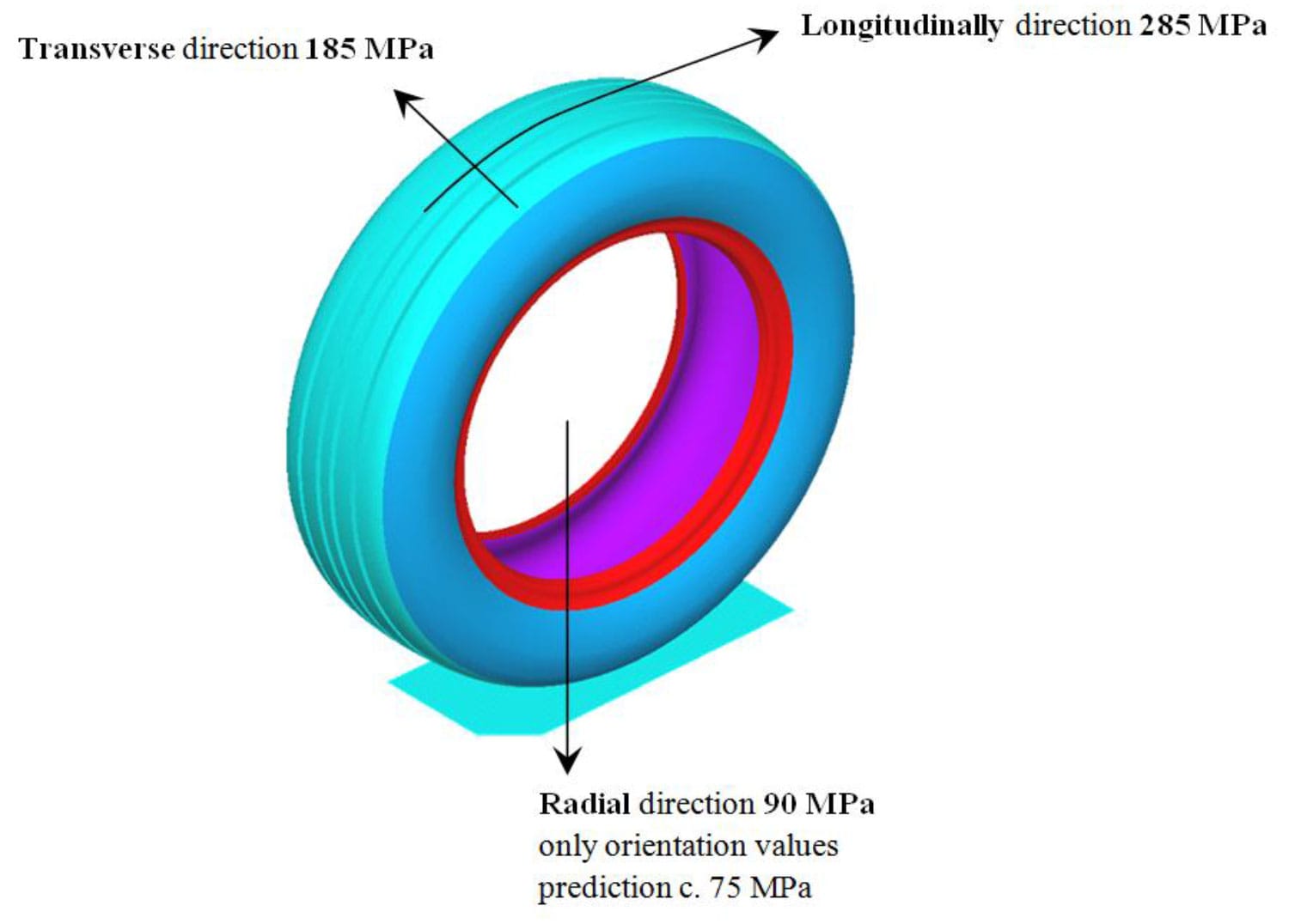
Fig. 11. Values of modules for definition of material parameters of tire-crown structure into computational models of tire 245/40 R18
Experiments of tire on statical adhesor
The experiments of tires are necessary for verification analysis between computations by Finite Element Method and experimental data. Namely the statical tire deformation characteristics are necessary for verification analysis. Also basic statical deformation characteristics of tires can be obtained from testing machine called statical adhesor.
On statical adhesor it is possible to obtain certain outputs as:
- Statical radius of tire,
- Radial deformation characteristic (dependence between vertical force loading of tire and radial deformation),
- Radial stiffness (in vertical force loading / radial deformation) in N/mm,
- Torsion (longitudinal) deformation characteristic (slip curve by twist moment),
- Torsion stiffness (in twist moment / rim angle) in Nm/° or longitudinal stiffness (in tangential force / tangential deformation) in N/mm,
- Contact patch – footprint shape and size with contact pressure colour distribution in contact patch by special pressure FUJIFILM Prescale® indicating film (film LLLW, pressure range 2–6 kg/cm2).
Measurements can be carried out at following main conditions:
- Loading (vertical force, twist moment),
- Size of radial deformation,
- Inflation pressure (under-inflation, overinflated tire, specified and practiced pressure),
- Unevenness (shape, surface roughness, material) etc.
Knowledge about contact patches and contact pressures is necessary for verification analysis between experiments and computations of tires for stress-strain analysis of tire with road (or unevenness).
The testing machine static adhesor consists of modern sensors and data logger:
- For force measurements are used tensiometer sensors by maximum load 2.5 kN,
- For deformation measurements are used potenciometric sensors,
- As data logger is used System DATAQ DI- 718B-US.
The tires must be prepared and experiments must be performed by special standards for tires [4–8]. On the statical adhesor it is possible to tests the tires from the radius of tire R13 to R18 and maximum width of tirecarcass c. 245 mm.
Eq. (1) were used for calculate of values of radial stiffness by standard [8]. The radial stiffness depends on inflation pressure of tire.

where:
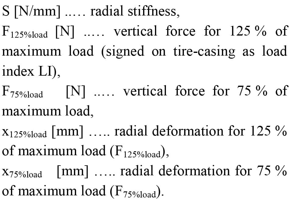
New formula Eq. (2) for calculating of values of radial stiffness, which is a modified standard formula (1) that was designed by author Krmela. This equation describes better real conditions of tire where maximum load during operation is 75 % of maximum load of tire.

The load speed of tire during experiments must be between from 0.8 to 2.5 mm/s by standard [8]. Experiments of tire 245/40 R18 on testing machine are presented in Fig. 12. The concrete tire has maximum tire pressure of 3.5 bar and maximum load of 730 kg (as marked on tire-casing). If required inflation pressure of this tire for concrete car is e.g. 2.6 bar that means this pressure is only c. 75 % of maximal tire pressure. Also maximum load for this ti
re pressure is not 730 kg but only 670 kg as load index (LI marking) by technical databook. Next e.g. for 2.9 bar maximum load is 730 kg. History of deformation process of tire near contact patch during loading for tire pressure of 2.6 bar is on the Fig. 13.
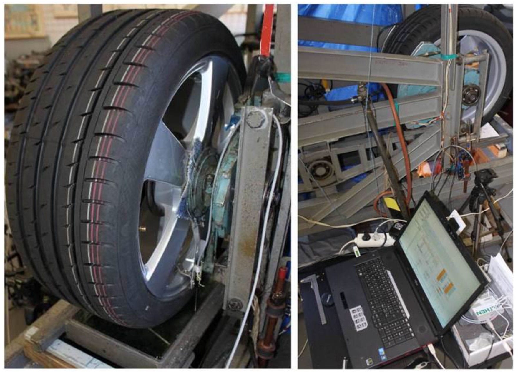
Fig. 12. Statical adhesor with tire 245/40 R18
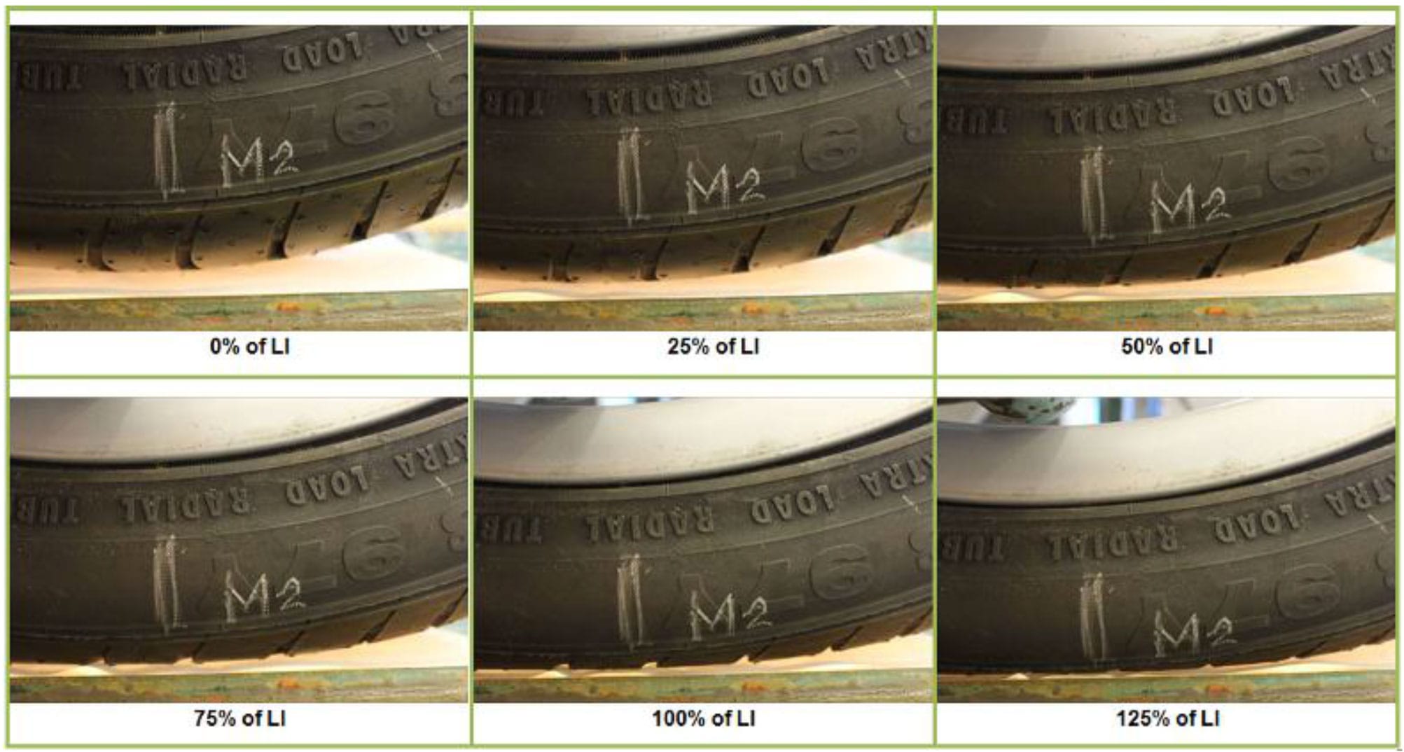
Fig. 13. Deformations of tire 245/40 R18 for different vertical loading for concrete percentage of maximum load (for 0, 25, 50, 75, 100 and 125 % of LI)
The radial deformation characteristic for tire pressure of 2.6 bar is on the Fig. 14. Average of the radial stiffness value by Eq. (1) is 280 N/mm and by Eq. (2) is 270 N/mm. Calculation of stiffness by Eq. (2) is better for description of real state of tire loading.
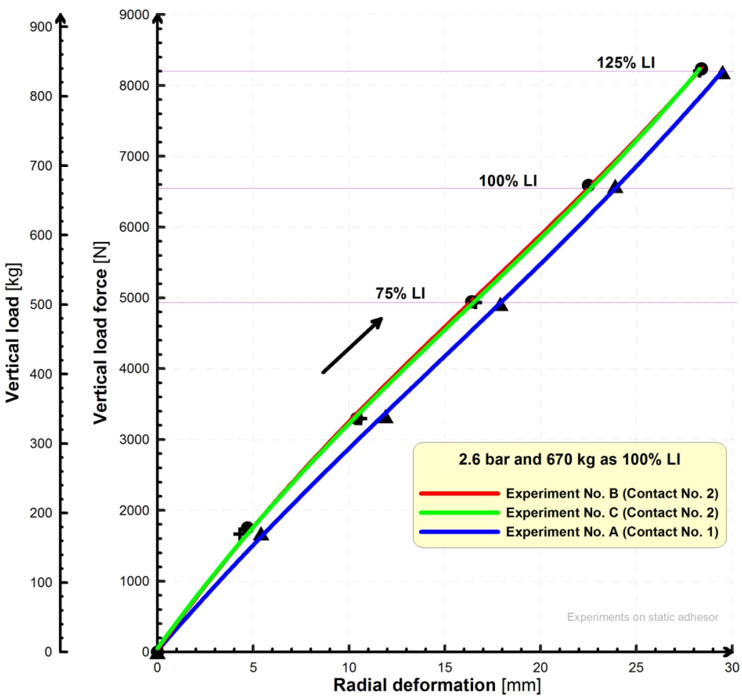
Fig. 14. Radial deformation characteristic of tire 245/40 R18 for tire pressure of 2.6 bar
The contact patches for different vertical loading are shown in Fig. 15 obtained by ink method. The Ultra Low Film Fuji Prescale® with exposure time of 2 minutes and 30 seconds was the standard used for contact patch with contact pressure distribution.
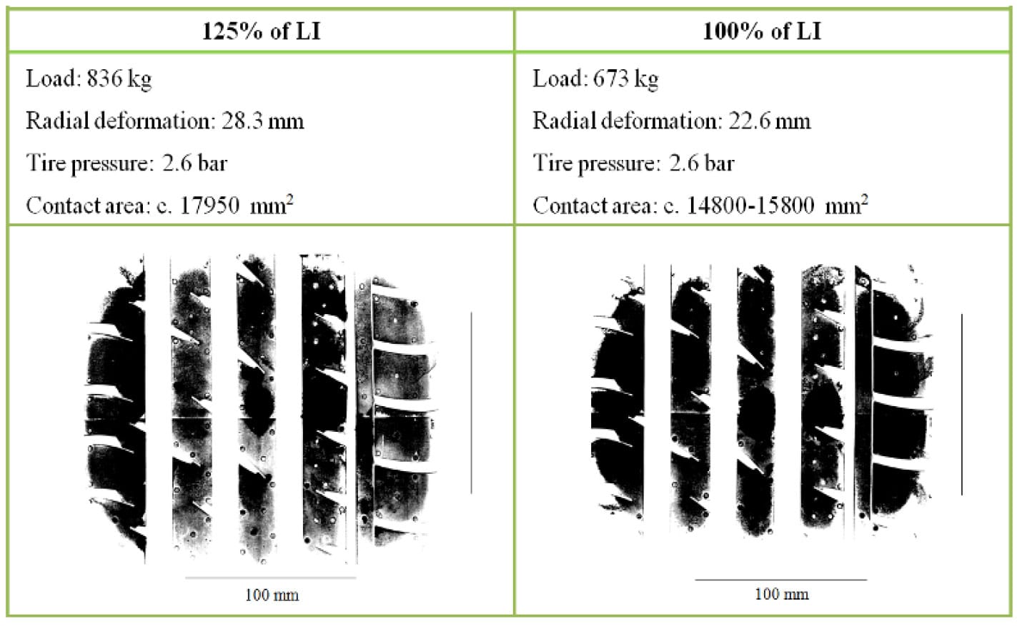
Fig. 15. Contact patches of tire 245/40 R18 for 100 and 125 % of maximum loading
In future in contemplation testing machine statical adhesor will be innovation in special system such as pressure measurement TireScanTM System [9] and then contact distribution in on-line mode is possible with complete analysis contact areas during continuous vertical load increase.
Maximum vertical loading on static adhesor is c. 1 100 kg. Then some tires with low load index (e.g. tire 165 R13 where maximum load is only 412 kg) are possible to test from 0 to 180 % of LI and this tire for small car can be overloaded with great deformation. Low-profile tires with maximum load index c. 102 are possible to test on statical adhesor.

Figure 2.3: Magenta sample table
Conclusions
For creations of computational models of tires (e.g. for strain-stress and modal analysis) it is necessary to have good knowledge about [10, 11]:
- Complete tire geometry parameters by scan of cross-section of tire-casing or by draw,
- Structure of tire-casing from macrostructure point of view,
- Number of composite layers and their geometrical configurations (namely thickness of layer and its width),
- Construction of steel-cord belt which are used in tire (as angle and number of cords per meter width of belt layer),
- Construction and material of cords into tire (with specification of construction),
- Material parameters of elastomer matrix and cords as reinforcements,
- Complete loading conditions (as inflation pressure in tire, loading force, shape of unevenness) etc.
For creation computational models of parts of tires (as model of belt layers of tires) it is necessary to have knowledge about [10]:
- Microstructure of interface between cords – elastomer after tire production (by microscopy) [12],
- Surface treatment of cords (as thickness of surface),
- Uniformity of layer of elastomer drift on cord surfaces (as adhesive bond),
- Next e.g. structural change into micro-locality of steel-cords – elastomer after degradation process as corrosion attack [13].
Radial stiffness of the low-profile tire 245/40 R18 is 270 N/mm for tire pressure of 2.6 bar. This value of stiffness can be used as input data to computational modeling of tire by analytical method. The contact area for tire pressure of 2.6 bar and vertical loading of 670 kg is c. 15 000 mm2. The deformation of tire-casing between rim and road is c. 22.5 mm.
Radial stiffness of tire is c. 300 N/mm for tire pressure of 2.9 bar. Tire pressure has got high influence on radial stiffness and radial deformation curve.
If this tire would be used in computational modeling with orthotropic material model for definition of composite parts of tire then modules of elasticity of steel-cord must be defined as input material data with these values: 285 MPa for longitudinally direction, 185 MPa for transverse direction and 90 MPa for radial direction.
In this paper the new formula for calculating of value of radial stiffness was designed. This formula Eq. (2) has got a practical meaning because it respects the real conditions of a loading tire during its use.
The laboratory of tire with testing machine static adhesor for static deformation of tires is complex laboratory with special program for analysis of contact patches at university in Czech Republic and Slovakia too, which enabling on-line measurements and evaluation all outputs from experiments of whole of tires for passenger cars.
References
- J. Krmela: Systémový prístup k výpoctovému modelování pneumatik I., Brno, 2008 (in Czech).
- J. Krmela: Communications 10(3) (2008) 61-65.
- D. O. Adams: A Comparison of CEN and ASTM Test Methods for Composite Materials, NTIS, US 2004.
- CSN 63 1001-4.
- CSN 63 1502.
- CSN 63 1554.
- CSN 63 1509.
- CSN 63 1511.
- TireScanTM System [available online on 30 August 2012], https://www.tekscan.com/ industrial/tirescan-system.html .
- J. Krmela: Recent 10(3) (2009) 333-336.
- J. Krmela, M. Müller, V. Tomanová, S. Rusnáková: Recent 10(3) (2009) 329-332.
- J. Krmela J., F. Pešlová, M. Muller, L. Hajduchová, V. Tomanová: Jemná mechanika a optika 55(2) (2010) 37-39 (in Czech).
- J. Krmela, V. Tomanová, F. Pešlová: J. Machine Manufact. 49(E3-E5) (2009) 111-114.


